
NOTE: This post is a work in progress. As long as it ends with “To be Continued”, please check back occasionally for updates.
The Garden Solar Light is a recurring interest of mine. It is often referred to as a Joule Thief but it is actually not. A Joule Thief attempts to extract usable power from an almost dead battery ( under 0.8 volts) while this technology is a switch pulsed voltage boost converter that operate above 0.9V. The somewhat mysterious little Chinese ASIC integrated circuits have been examined by a number of people since I first posted about the subject in 2012. Recently, a fellow member of the Asheville based Western North Carolina Linux Group (WNCLUG) re-sparked my interest in the topic. Our ultimate goal is a modified Garden Light that can power an ATTiny85, radio transmitter and sensor for periodic transmission of sensor data.
This time I decided to spend some time delving more into the somewhat mysterious little Chinese integrated circuits used in the solar garden lights so as to, hopefully, make more informed design decisions in the final project. There is a plethora of similar Chinese Garden Light integrated circuits and, despite having different identifying part numbers, they seem to all be similar of each other, despite some variation in pin assignments and capabilities.
A pretty good list of them is HERE. Despite their similarities, one reason for the overabundance choices, besides competition between manufacturers, is to accommodate for different current and voltage applications as well as other improvements, such as over discharge protection. Some of the improvements are patented. I found an interesting list of Garden Light ASICs on 52rd.com in a post by user yuxinzxs. See the English translation of the Garden Light portion at garden-light-asic-list The YX8018 appears to be the granddaddy of them all. The YX8018 and the QX5252F seem to be the most commonly encountered. The QX5252F is manufactured by QX Micro Devices Co., LTD of Shenzhen, China who holds several patents for these types of chips that prevents the battery from being overly discharged in order to prolong battery life – Chinese patents 200910107832 and 200910107063 and 200910107064 for high efficiency charging.
By the way, before I start ignoring the YX8018 in favor of the QX5252F, if the YX8018 interests you check out SparkFun’s interesting project for creating a soil moisture sensor using a Garden Stake that uses the YX8018. It is simple but informative. If the soil is damp, the LED is out. If the soil is dry, the LED is lit. Read the SparkFun article at THIS-LINK.
The YX8018, like most of its cousins, come in 4 pin transistor SIP-4 package identified as TO-94, which can be seen in Figure 1, below. The internal schematic of these Chinese voltage booster chips is elusive. However, there are a few semi-schematics of the internals, one of which was posted in an Instructable by Dave Kruschke and it appears a little more complete than others that I have discovered – However, the slightly simpler internal schematic posted by burger2227 (Ted from Pittsburgh) is quite adequate and is shown immediately below in Fig. 1.
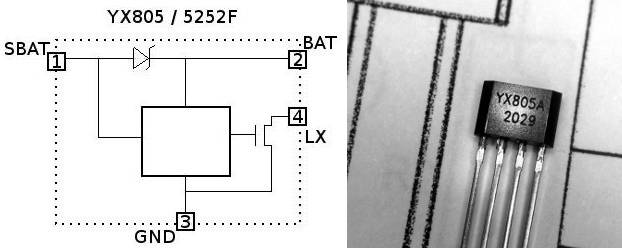
Fig. 1: YX805A
Below is a somewhat more detailed internal view from a manufacturer datasheet.
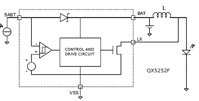
Fig 1a: QX5252F Functional Block Diagram
The integrated Shottkey diode between the solar panel on pin SBAT and the battery on pin BAT is part of the charging circuit and also blocks the battery from biasing on the controller/oscillator (white box in center). The gated oscillator runs at a ~200KHz driving an open drain NMOS switch ( output on pin LX ). The non-sinusoidal pulses on LX pin pulse the external inductor (Figure 2) at the ~200kHz rate and the resultant field collapses boot the voltage presented to the LED in the manner of a Joule Thief. The Instructable by Dave Kruschke has a nice explanation of how the inductor creates the voltage boost. Each pulse causes current to flow into the inductor which creates a magnetic field around the inductor, that is, in essence, stored energy. When the pulse ends, current flow stops, the inductor’s magnetic field collapses and its energy is returned back into the circuit, adding to, or “boosting” the voltage.
Voltage Boost via Coil Field Collapse
I purchased some YX805A chips through eBay and, as the first step, I am replicating a Garden Light’s circuitry on a breadboard. I configured the basic circuit in Figure 2, below, except for the solar charging portion. For now I am only testing the voltage booster section with an alkaline 1.57V. battery.
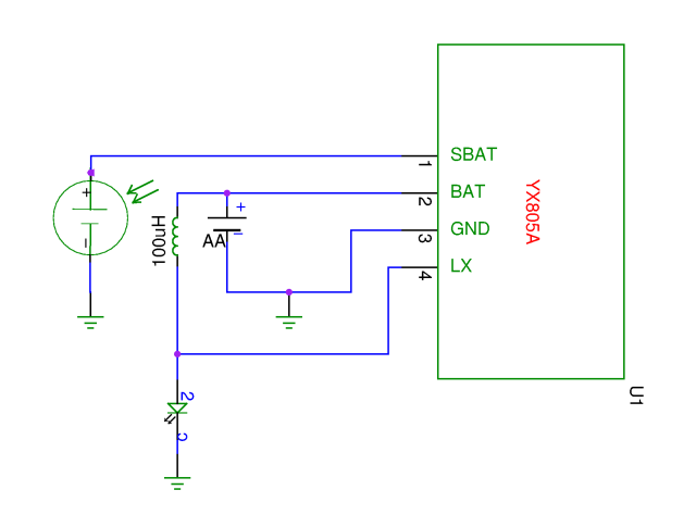
Fig. 2: Initial Test Circuit
My initial breadboard test circuit is shown in Figure 3, below.
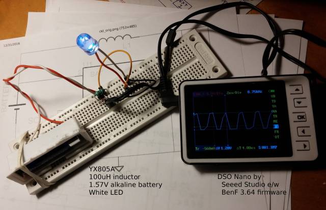
Fig. 3
I used a YX805A chip with a 100uH inductor and a white LED. The battery used was a AA size alkaline battery that measured 1.57V with a voltmeter. This configuration oscillates at 215kHz. See Fig. 3, below. Most white LEDs require 3-Volts to conduct/illuminate, and typically operate in the 3.2V to 3.4V range. The output measured 3.6V between ground and LX, the pulsed output. At this point the 215kHz is only usable for the LED light application, where the human eye cannot detect the oscillation. Rectification and stabilization will be needed before the output is usable for anything else.

Fig. 4 – YX805A with Alkaline Battery
With a 1.29V NiMh battery the oscillation frequency was slightly different, at 226kHz, see Figure 5, below. However, the oscillator isn’t that stable so both the alkaline and NiMh batteries produced the expected approximate 200kHz frequency.
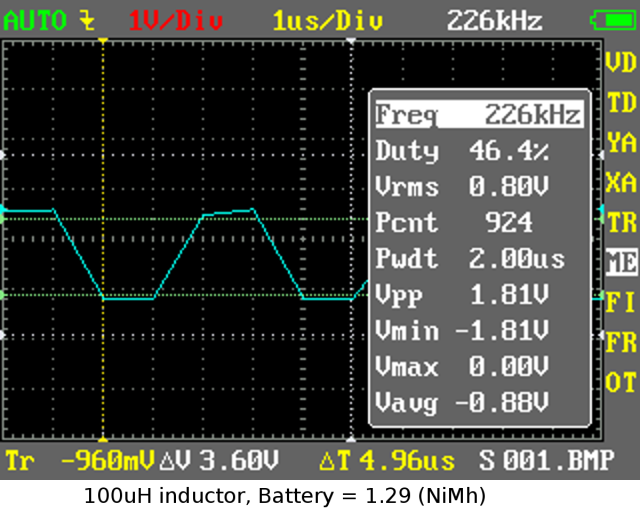
Fig. 5: YX805A with NiMH battery 100uH inductor
With the same circuit but using a 5252F ASIC instead of the YX805A. Results are very similar as can bee seen in Figure 6, below. The frequency was somewhat higher at 282kHz and the waveform even less of a square wave than with the YX805A. Nonetheless, quite similar and equally usable.
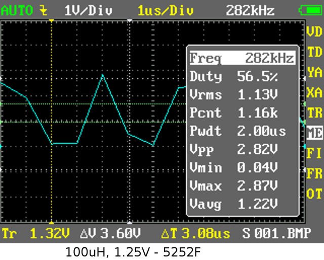
Fig. 6: 5252F, 100uH, 1.25V NiMh
My next incremental step was to rectify and stabilize the circuit’s output to 5 volts. At this point I have not installed the solar cell charger – that will come later.
The schematic shown in Figure 7, below, provides 5.18VDC across a megohm load (multimeter), at 45ma (only multimeter’s load in Ampere mode) from a fully charged 1.29V NiMH battery. With a 33uH inductor it supplies 50ma. These readings match the YX805A datasheet in that the smaller inductor value does produce more current (290kHz) but the values differ from the chart. Possibly this is due to my using a signal diode instead of the datasheet’s white LED, or it is due to the particular manufacturer of my YX805A.
When measured across, and through, a sustained 19Ω load, meaning starting from a discharged capacitor, I see 5.1VDC at 580uA. Conversely, if the capacitor is fully charged prior to applying the load, I measure 5.1V @ 25ma. This test was using a 33uH inductor. When measured across, and through, a 1kΩ load with a charged capacitor I see 5.1VDC at 5.1mA. A subsequent test, with the circuit moved to a new breadboard and using a 22uF filter capacitor yielded ~17mA through a dead short (ammeter).
To be usable as a power supply, the load may need to be intermittent in order to charge the capacitor between higher current cycles. Fortunately, Dolen Le has researched and documented exactly how to do this with the ATTiny85.
The solar charging portion is not part of the initial tests. Without the 5.1V zener the output voltage is 8.5V.

Fig. 7: Basic 5V Supply Added
Using the oscilloscope I measured the 5V ripple at .05V – time to see what it can do!
I programmed an Arduino NANO with the one-second Blink program and connected it to be powered by the Garden Light Redux – Power Supply. It worked perfectly (for now) with the 1000uF capacitor providing a current reserve. A short video is below that shows the Arduino running under Joule Thief power from one NiMH AA battery.
UPDATE: Something changed and I can no longer replicate these results with the YX805A circuit described above, meaning that the NANO will no longer run with that power supply. Currently, I am seeing much less current than before and it isn’t enough to operate the Arduino NANO. Trying to see what was happening I put scope leads across the Arduino NANO power leads and then connected the my Garden Light DIY 5V Power Supply. What I see it starting at 5.2V and within 140ms voltage was down to 3V with a precipitous drop after that. See Figure 8, below. I don’t know what changed – I have replaced all components, one at a time between tests, except for the Arduino NANO. Changing the NANO is on my list. Meanwhile, I compared current load with “this” genuine Arduino NANO e/w FTDI serial I/O and a Chinese Arduino NANO e/w CH340G I/O – both running a “blink” program. Idle is the low current and LED-on is the high current:
- genuine Arduino NANO e/w FTDI serial I/O – current 25-to-30mA
- Chinese Arduino NANO e/w CH340G I/O – current 22-to25mA
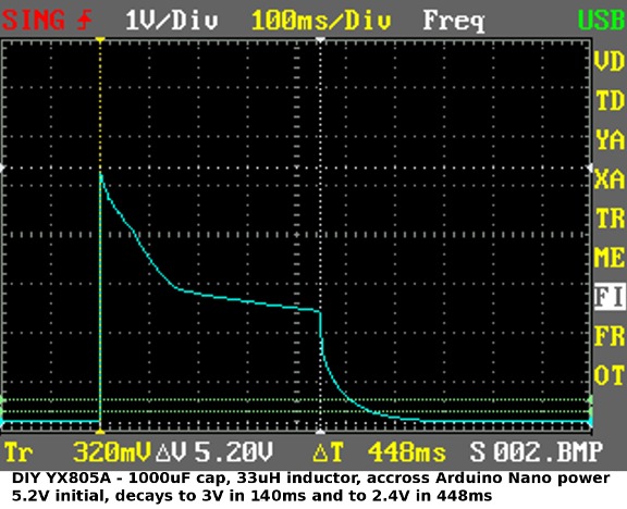
Fig. 8: Voltage drop on NANO Connection
Seeing that this circuit wasn’t going to be adequate to power the Arduino NANO, I did some measurements using the BLINK program in an ATTINY85-20SUR surface mount package – see video below. Idle current consumption is 8.7mA and with the LED on it is 11.5mA. Better, but still a challenge for the ATTiny85 and a transceiver plus sensor. The supply still needs work.
I made some changes and have a working circuit again! I hate the unexplained. Anyway, I switched to a QX5252F ASIC, 100uH inductor and a Schottky diode. See figure 9 below. I’m seeing 5.1V with 125mA on a dead short and 43mA through a 1000Ω resistor. This circuit correctly runs the ATTiny85 running Blink in the video immediately above.
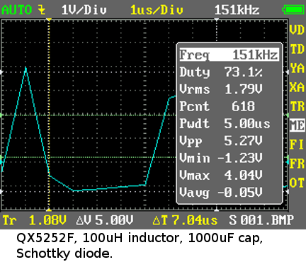
Fig. 9: QX5252F & 100uH inductor
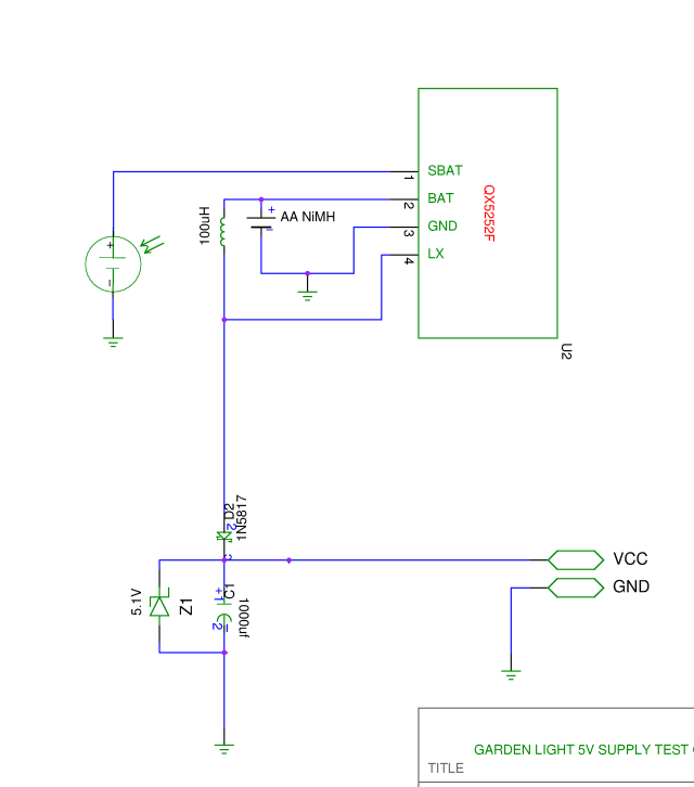
Fig. 10: QX5252F Schematic
I didn’t like the unexpected change in performance, so additional testing is in order before I can say that this circuit is solid. A future step will be to more extensively test the basic solar charging circuitry – I have already briefly tested it. After that, I may add and test Ivan Nechayev’s charge regulation circuitry.
Keep watching this post to expand – it is NOT finished. Other posts may be used will wait for other aspects of my project, such as adding the radio transmitter and sensor. Until then:
To Be Continued

I found your interesting article while searching for info on the YX8018 chip. Good reading. I’m fiddling with YX8018’s myself while building a solar powered night light for the outhouse at a favorite campground. Have the PCB from a garden light on a breadboard and am experimenting with different size inductors to see the effect on battery drain and output voltage. I bought a dozen garden spotlights on closeout for $1 each and I certainly got a lot of useful parts for my money. Dodgy looking NiMh AA’s, leds, solar cells, tiny PCBs with the chip on them and quite nice spotlight heads with three leds each and faceted plastic reflectors. The outhouse light will be built into a small and nondescript plywood box screwed to the outhouse ceiling. Solar panel will be four cells salvaged from the spotlights connected in parallel and stuck down to a piece of perspex with RTV silicone for weatherproofing. Battery will be a C sized NiMh with 2200mAh capacity which should give a bit of reserve to cope with a succession of dull days. It’s all fun and nice to do something for other campers. The most interesting part will be seeing how long my solar charged nightlight lasts before some creep steals it.
LikeLiked by 1 person
If you were going to build anything from scratch I recommend that instead of the YX8018 chip that you instead used qx5252 chip. It provides significantly more current.
LikeLiked by 1 person
Hi, thanks for info on the qx5252. However, batteries are no good in the below freezing temps experienced in many places during winter.
Therefore we need such an ASIC chip that is designed for the lithium titanate battery which is 2.4v nominal, 1.7v (?) max discharge and 2.8v for charge. Such a chip would allow solar charging to FAR below freezing, and the LTO battery lasts “forever”.
LikeLike
Pingback: P08_01_00 Solar DC-DC converters – Kiono Kitse
Pingback: Dead Nimh Battery - EZ Battery Reconditioning