
As I continue to experiment with voltage boost converters I was intrigued by some Chinese DC-DC Boost Converter modules. There are several different types and module configurations, depending upon the manufacturer and chip type. I opted to buy a couple of modules made by Shenzhen Canton-Power Electronic Technology Co.,Ltd a four year old Chinese company which, based on their website photos, is a pretty small shop with about a twelve workstation capability.
I ordered two 0.8~3v to 3.3v Step Up Boost DC to DC Converters from a Hong Kong seller on eBay. I paid more for these to get them faster. Interestingly, I ordered what the Hong-Kong seller identified as a WTI-0833 module. However, what was delivered was a CE012 module – AND – it was delivered by a USA company based in Virginia. While the WTI-0833 and CE012 are physically different PCB layouts they appear to functionally equivalent and both use the 2108A ASIC. Canton-electronic sells the CE012 on eBay in single quantities for $1.59, delivered. The 5V output version is available via aliexpress – $1.26 in a quantity of eight, which I also ordered and it was delivered as I write this. Both of these modules utilize the 2108A boost chip. The 3.3V version is marked 2108A 1552/32 while the 5V version is marked 2108A 1620/50. They both have the following manufacturer’s logo on the chip:
![]()
| 2108A-1532/33 – 3.3 Volt Version | |
|---|---|
| Input 0.8 ~ 3.3V | output 3.3V |
| Maximum output current | 500 MA, |
| Start Voltage 0.8V | Output Current 10MA |
| INPUT 1-1.5V | OUTPUT 3.3V 50-110MA; |
| INPUT 1.5-2V | OUTPUT 3.3V 110-160MA; |
| INPUT 2-3V | OUTPUT 3.3V 160-400MA; |
| INPUT above 3V | OUTPUT 3.3V 400-500MA; |
| Boostfrequency 150KHZ | efficiency 85% . |
| 2.54mm pin pitch | Breadboard friendly. |
| Excluding Pins | 11mm x 10.5mm x 7.5mm |
| Weight | ~1.2g |
| 2108A-1620/50 5V Version | |
|---|---|
| Input | 0.9 ~ 5V, output 5V |
| Maximum output current | 500 MA, |
| Start Voltage 0.9V | Output Current 10MA |
| INPUT 1-1.5V | OUTPUT 5V 50-110MA; |
| INPUT 1.5-2V | OUTPUT 5V 110-160MA; |
| INPUT 2-3V | OUTPUT 5V 160-400MA; |
| INPUT above 3V | OUTPUT 5V 400-500MA; |
| Boostfrequency 180KHZ | efficiency 85% . |
| Operating ambient temperature | -25~+85 Degrees Celsius |
| 2.54mm pin pitch | Breadboard friendly. |
| Excluding Pin Size | 11mm x 10.5mm x 7.5mm |
| Weight | about 1.2g |
The DC-DC converter package is a rather odd looking SOT89-3. The manufacturer of the chip was quite elusive but I was able to identify them. The 2108A DC-DC converter chips are manufactured by Nanjing Micro One Electronics as the ME2108 DC-DC Step Up Converter. The specification (in English) is available HERE.
I used a breadboard to connect a 1.3V NImH battery to the 2108A-1532/33 and measured first with a multimeter and then my little digital scope. The multimeter showed a nice, steady 3.3V. Next I looked at the 2108A-1532/33 output with the scope – very stable 3.3 Volts – see Figure 1, below. I added no filtering capacitor – this is with just the module.
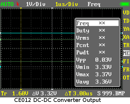
Fig 1: Output of CE012 DC-to-DC Converter
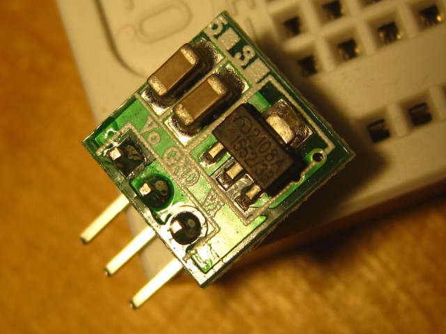
Fig 2: CE012 DC-DC Converter Module – back view
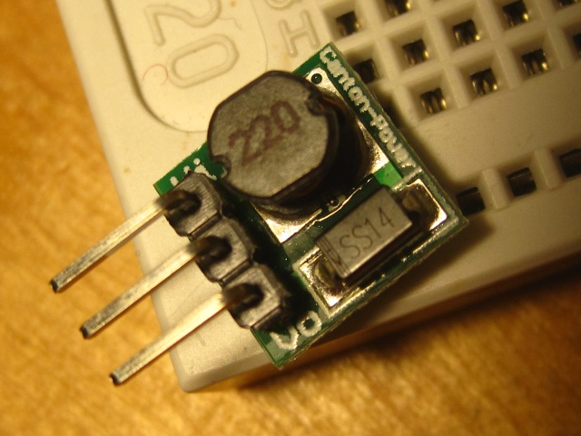
Fig 3: CE012 DC-DC Converter Module – front view
Seeing a good steady 3.3V on the CE012’s output and given the specification’s output current rating of 50 to 110mA with this battery, I connected it to a breadboard with an ATTINY85-20SU loaded with the Arduino BLINK program – see Figure 4 below.
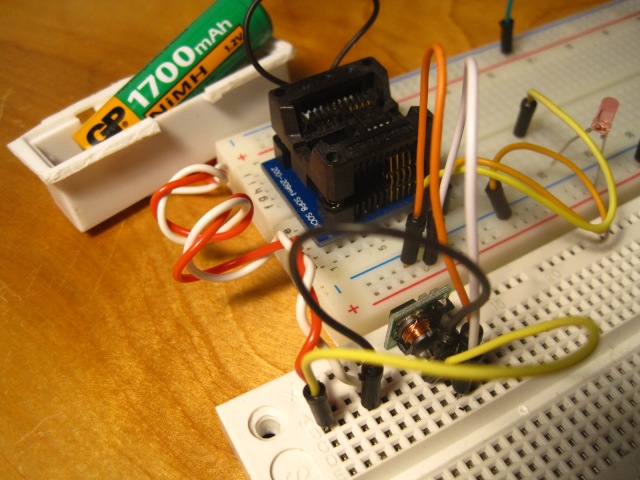
Fig 4: Test setup for CE012 powering ATTiny85
The CE012 module fueled by the 1.3V AA NiMH battery immediately cranked up the ATTINY85-20SU loaded with the Arduino BLINK program. See the video posted immediatly below.
With nothing connected to the CE012’s output the battery was sourcing 0.09mA. When the CE012 was powering the ATTINY85 the battery was sourcing 43mA to 75mA (59 mA average) depending on the LED’s state. With the 1,700mAh battery fully charged this circuit could run a theoretical maximum of 28 hours before exhaustion. Please note that this is 1.3V battery current and that I did not measure the current at 3.3V consumed by the ATTINY85.
The 5V version drew 55mA to 64mA depending on the LED’s state. With nothing connected to the 5V CE012’s output the battery was sourcing 0.5mA. Please note that this is 1.3V battery current and that I did not measure the current at 5V consumed by the ATTINY85.

Thanks much for the info. Info on these tiny modules was hardly available.
LikeLike
Thanks for the detailed research and analysis. I’ve been deciding which boost converter I want to use in a project and this was really helpful.
LikeLike
43mAmps? How on earth is that possible with an Attiny85? I thought that they can run comfortably on ca. 1-2mA @ 1MHz. What’s happening here? It’s a genuine question…
LikeLike
pfabri, That is the 1.2V battery current. I didn’t measure the boosted 3.3V or 5V current being fed to the 8MHz ATTiny85.
LikeLike
Alright, that makes sense then. Thanks for the reply.
LikeLike
Warning: I have ordered some of these boost converters via ebay and got some with wrong ICs labeled SO-1 JHZYE17. So pay attention!
LikeLiked by 1 person
I’d be interested in a similar test of Microchip mcp1640t
LikeLike
Hi, I have created a Fritzing part for this converter: https://github.com/jablan/fritzing_parts
Also, I have bought it (3.3V variant) to try to power ESP8266 using two AA batteries. It doesn’t work, seems that there are current spikes that this little converter can’t provide. It powers Arduino Pro Mini without problems though.
LikeLike
This part’s specs are 1.5V input. Did you wire the AA Batteries in series or parallel?
LikeLike