Single Coil Latching Relay Test

I am using a latching relay in a project that I am working on AND I wanted to test my circuitry before a PCB is made. Consequentially, I did a breadboard of the relay portion of the circuit and tested it using an Arduino NANO to drive the relay test.

This test is of a single coil latching relay: KEMET EC2-3SNU
https://content.kemet.com/datasheets/KEM_R7002_EC2_EE2.pdf

This test is using a 5V Arduino NANO but all other circuitry is 3V3.
Switching the Arduino output pins LOW applies an open collector ground
while switching the Arduino output pins to HIGH applies 3.3V via discrete
pullup resistors.

NOTE: Since the contact load is resistive no snubber circuit is used.
NOTE: The EC2-3SNU set/reset Pulse Width requirement: > 10 ms

CONNECTIONS:
NANO-2 -to- EC2-3SNU pin 1
NANO-3 -to- EC2-3SNU pin 12
LED-D2 -to- EC2-3SNU pin 3
LED-D1 -to- EC2-3SNU pin 5

The source code resides at: https://pastebin.com/sjkr95p0

The video link below shows the test.

The coil is pulsed to SET with 3V@33mA for 15ms followed by 20ms of no current (quiescent), with by a pause of 3-seconds, then the polarity is reversed and pulsed to RESET again followed by 20ms quiescent then repeated in an infinite loop. If you listen carefully you can hear the relay click. The LEDs follow the contact operation.

Video Link: https://youtu.be/3npKrtUg3bo

I did a re-test of this relay to do some more readings. This test of the EC2-3SNU using Arduino driven 20ms pulses through a ULN2801A which has an open-collector output. The 90Ω relay coil has 20 ohm pull-up resistors to nominal 3.3V. The measured pulse is 20ms. Peak-to-peak square-wave voltage is 1.62V. Figure 1, below, was captured with a FNIRSI oscilloscope.

Posted in Arduino, Electronics, hardware | Tagged , | Leave a comment

All tied up with KiCad Net-Ties

A net-tie is a special footprint that permits dissimilar net-classes to connect. Without a net-tie Kicad’s schematic editor won’t allow the connection. This isn’t much of a problem for most PCBs but becomes important when a design has multiple power traces with different amperage requirements, necessitating multiple different trace widths that need interconnection, in some situations.

I am involved in making a PCB with six (6) different voltages and with different current requirements. In order to get the PCB to layout correctly it is preferable to assign net-classes to each voltage and, when it will affect the trace widths, traces with different currents. Kicad will refuse to connect dissimilar netlists, although it will not complain about connecting net-classes to GND, with disastrous results. The common GND connections will back-feed a connected net-class to every other connection to GND, everywhere on the PCB. An example of this back-feed is shown in Figure 1, below. NOTE: The fat green traces were to visually denote a different trace width. Ultimately, I switched back to the normal schematic line width but used red color to denote a larger trace width.

Figure 1

The solution is to separate the net-classes with a net-tie. While this isolates the net-classes, it connects them on the copper layer. Below is an example where I have connected two 28V traces where one needs a very fat 3-Ampere trace of 1.367mm and the other is a 28V trace that needs a 0.6A trace of a generous 0.1524mm. (yes, this an strange circuit but there is a legitimate reason). The schematic is shown in Figure 2 while the physical traces are shown in Figure 3, below.

Figure 2

Figure 3

So, what is a Net-Tie? It is a footprint of two or more pins that are connected by copper layer polygon that has a “magic” Keyword of “net tie”. It’s a bit of a kludge, but it works. A negative is that all net-ties currently put down copper (the polygon). Rumor is that in a future Kicad release there will be a virtual net-tie that doesn’t lay down copper but simply permits a dissimilar net-class connection while isolating the net-classes. The footprint of the net-tie used in the above example is shown in Figure 4, below.

Figure 4

Kicad’s net-tie library is rather small and I ended up having to make several new net-ties to fit the needs of this unusual PCB. It isn’t hard. Just use the Footprint editor to modify an existing net-tie and then save it locally. In my case, I use a local repository for a large number of parts that I use that are not in the Kicad library.

I encountered another oddity that I needed to create. I wanted to reduce the trace-width of a high current trace by running two traces of half the needed size on front and back. (Internal would be a wider trace than external but the principal is the same). Below, in Figure 5 is a trace for this situation. This helps with real estate space consumption for long higher current traces – obviously only useful in “some” situation. I had to “make” both the symbol and footprint because Kicad’s library has nothing like this. It isn’t difficult – go for it.

Figure 5

That wraps it up. Net-ties have a useful place so try them out if you have a board that needs them.

Posted in Electronics, PCB Design | Tagged | Leave a comment

Convert Dollar-Tree LED Nightlight from White to Red?

I wanted a red LED nightlight. None were available in the local stores so I decided to convert a Dollar-Tree store white led nightlight to red. I chose a manually switched on/off version. These DollarTree nightlights are not really nightlights. They are only bright enough to be a guide light. Anyway, I wanted to see what was inside a one dollar nightlight. The light is a L’Image Home Products Inc. Model 30310732. It shows Intertek ETL Listed mark of 5010183.

Figures 1 and 2 show the light post-conversion but the red led is the only difference.

Figure 1
Figure 2

The mechanism is very simple. Figure 2, above, shows the toggle switch in the “on” position. In this position, the interior portion of plastic toggle presses a copper strip against the line-side of the polarized (narrow) prong (USA standard 15A, 120V NEMA1). There is a rather strong spring that provides the switch’s positive action and pressure to press the copper strip onto the power plug’s prong. The construction seems sturdy and safe, except if the single screw holding everything together were to fail there is a potential for the spring to move into a compromising position that could cause a short. I believe that gluing the lamp body’s two sides together would be a good safety addition to overcome this risk potential. A blowup image is Figure 3, below.

Figure 3
Figure 4

The circuit is ultra-simple, as expected. The AC is rectified to half-wave using a diode, creating a 53V (1/2 sine wave pulsed DC). The 53V is dropped using two resistors in series – 24k Ohm and 100 Ohm for 24.1k Ohms in total. Circuit current will be 2.1mA which yields a 0.108W power dissipation. I cannot tell the power rating of the resistors but they “should” be 0.124W, and probably are based upon the general quality of the build. Two Milliamperes makes for a pretty weak light from this led. I used a “bag of generic 3mm red leds” from China so I can only assume generic values of a max drive current of 20mA and a forward voltage drop of 2V. The 2mA available is feeble for this led but increasing the current would require changing the resistors to a higher Wattage and that just isn’t worth it.

Oh well, I don’t have a red nightlight but at least I have a guide light in red and the knowledge of what is inside this DollarTree product. Meanwhile I found some nightlights on-line that use red leds, not white leds with red lens, and have ordered some. BTW – I want red nightlights because they are better for nightlights while sleeping.

Posted in Electronics, hardware | Tagged , , , | Leave a comment

KiField saved me a ton of manual KiCad editing

I am still using KiCad 5.1 because I cannot risk having version 6 change my custom libraries (I have a lot) since I am still involved in a large, to me, project, which, for privacy I will simply refer to as the “project”. It isn’t “my” project – I am consulting on it. I have entered the point of selecting a fabricator that will make the board AND assemble the boards – just a few at first for functional testing. I’ve had problems finding a suitable USA fabricator – the two that I have existing accounts with seem to have vaporized with marginally functional websites and no response to my queries. Possibly the COVID shutdown killed, or nearly killed their businesses.

Years ago I had Seeed make some boards but not assembly, although they do offer assembly. Those boards were nicely made. I decided to price a different Chinese fabricator. While they had no problem with my uploaded design files the BOM is another story. While reformatting KiCad’s BOM output to match what Pcbway wants isn’t a big deal, I wanted to use LCSC parts for the resistors, capacitors, coils, etc. and few select ICs. I “may” have to ship them a few specialized ICs for assembly. The problem is that I needed the LCSC part numbers for about eighty parts. I REALLY didn’t want to have to hand edit eighty parts using eschema.

I searched around and found just the tool that I needed to semi-automatically update all of the parts in my KiCad project’s eschema sch file. It is Dave Vandenbout’s “KiField”. I won’t explain the details, for that see the documentation in Dave’s github at https://github.com/devbisme/KiField or at https://kifield.readthedocs.io/en/latest/usage.html. The synopsis is that KiField is a utility for manipulating part fields in KiCad schematic files or libraries. KiField can extract all the component fields from a schematic or library and place them into a spreadsheet for bulk editing, after which you can insert the edited values from the spreadsheet back into the schematic or library.

Here is what I did.
– I uploaded the project’s BOM to LCSC’s website BOMtool at lcsc.com. This creates a spreadsheet-like page(s) which as every part along with the LCSC part number. This can be downloaded as a csv file, which I did. Oddly, LCSC doesn’t show the part designation/Reference unless to name that column “description” before uploading the BOM.
– Next I used KiField to download all of the parts to a new “extracted” cvs spreadsheet file using this syntax: kifield -x ..//project.sch -i project-extracted-fields.csv
– Next, after making sure that the sort was identical, I copied the “lcsc part number” column from the downloaded LCSC spreadsheet to a new LCSC_PN column in project-extracted-fields.csv (open in spreadsheet program first, of course).
– The final step was to populate the project’s appropriate 80 parts with the LCSC part numbers with the following command: kifield -i ..//project.sch -x project-extracted-fields.csv -w

That’s it. KiField saved me a ton of manual work. Thank you Dave Vandenbout!

Update – Using Kifield with KiCad v6.0.6

I have migrated an old project from KiCad v5.1 to v6.0.6. I needed to change some of the hidden fields but it didn’t go well with KiField. Unlike when using KiField with KiCad v5.1, every new field or field entry would be marked “visible” and the schematic became quite cluttered.

The KiField documentation states:

To manage the visual clutter of a schematic, you can set the visibility or invisibility of inserted fields as follows:

Prefixing the header of a column with [I] will make every entry in that column invisible. Prefix with a [V] to make them all visible.

Any values in the column prefixed with [I] or [V] will override the column heading.

Without prefixes, any new field is invisible by default.

Existing fields retain whatever their original visibility/invisibility was.

I did not understand this instruction and thought that the brackets were just for emphasis in the instructions. No, you must use the brackets!

If a new spreadsheet field column or just a new item in an existing field column is edited into the spreadsheet that is to be inserted into the .kicad_sch file then the [I] must be explicitly added as a prefix. Otherwise, the default is visible.

As an example, if a new column named WIDGET is added to the spreadsheet and you don’t want it to be visible on the eeschema schematic displayed, then the spreadsheet column must be named [I]WIDGET

The “[I]” is an instruction for KiField and it won’t appear in the schematic – only WIDGET.

All of this is also true if you add a new entry into an existing field column. So, for example, a new entry into existing a column named MPN would require that the existing column be renamed [I]MPN IF you want all in MPN to be invisible.

Posted in Electronics, Linux, PCB Design | Tagged | Leave a comment

KiCad Local Library Management – my spin on it

I am by no means an expert on KiCad. In fact after using gEda-PCB and pcb-rnd for years I only recently needed to work on someone else’s project that requires KiCad. Actually, I have been away from PCB design for over a year due to moving between states followed by some other demands on my time.

I had tried out KiCad some years ago but abandoned it after finding it not to my liking. However, the KiCad current version 5.1 is vastly improved and now is a very workable EDA system. It is not without some quirks but very workable nonetheless. One thing that bugs me about KiCad is its local user symbol library management. By this I mean symbols that I create when none exist in the KiCad core library, which for my current project, is a lot. Before I describe what I have done to make it easier for me I’ll explain a little about how KiCad 5.1 handles its libraries. CAVEAT – my systems use Linux exclusively.

KiCad’s libraries are stored in accordance with path pointers, shown in Figure 1, below. Note that I added those beginning with “MY_…”.

Figure 1: KiCad library paths

The KiCad release core symbol library is stored as library category packs in “/usr/share/kicad/library” and its release core footprint (modules) library is stored as one file per footprint (module) in folder “/usr/share/kicad/modules (more about modules later).

KiCad normally handles user locally contributed libraries on a project basis. If you create a new or modified footprint you can save it into the release core symbol library (not recommended) if you have write permission. The preferred way is to save it to a project symbol library file that resides in the project folder. There is one such project symbol library file regardless of how many symbols you save to it. For example, see Figure 2 below. It is a single symbol library file, such as a project symbol library file, with two symbols: 1053071202 and CON_1P.

EESchema-LIBRARY Version 2.4
#encoding utf-8
#
# 1053071202
#
DEF 1053071202 P 0 10 Y N 1 F N
F0 "P" 350 250 60 H V C CNN
F1 "1053071202" 350 150 60 H V C CNN
F2 "" 400 -60 60 H I C CNN
F3 "" 0 0 60 H V C CNN
$FPLIST
 CON_1053091202
$ENDFPLIST
DRAW
P 2 1 1 5 150 0 350 0 N
P 2 1 1 5 200 -200 500 -200 N
P 2 1 1 5 200 -100 350 -100 N
P 2 1 1 5 200 100 200 -200 N
P 2 1 1 5 350 -100 400 -133 N
P 2 1 1 5 350 -100 400 -67 N
P 2 1 1 5 350 0 400 -33 N
P 2 1 1 5 350 0 400 33 N
P 2 1 1 5 500 -200 500 100 N
P 2 1 1 5 500 100 200 100 N
X 1 1 0 0 200 R 59 59 1 1 U
X 2 2 0 -100 200 R 59 59 1 1 U
ENDDRAW
ENDDEF
#
# CON_1P
#
DEF CON_1P J 0 40 Y Y 6 L N
F0 "J" -50 150 50 H V C CNN
F1 "CON_1P" 0 -150 50 H I C CNN
F2 "Connector_Molex:Molex_Nano-Fit_105314-xx06_2x03_P2.50mm_Horizontal" 0 0 50 H I C CNN
F3 "" 0 0 50 H I C CNN
DRAW
S -100 100 100 -100 0 1 0 N
X 11 1 -250 0 150 R 50 50 1 1 U
X 12 2 -250 0 150 R 50 50 2 1 U
X 13 3 -250 0 150 R 50 50 3 1 U
X 20 4 -250 0 150 R 50 50 4 1 U
X 23 5 -250 0 150 R 50 50 5 1 U
X GND 6 -250 0 150 R 50 50 6 1 U
ENDDRAW
ENDDEF
#
#End Library

Figure: 2

Now I have used the project symbol library method but I also wanted a global library that wasn’t part of the release library since that can be lost when KiCad is updated to a new release. I also wanted “my” global symbol library to be accessible from more than one of my computers so I placed it on a networked folder. In my case on Google Drive synced by InSync but whatever networked folder that you use would suffice.

So, I created “my” global symbol library in my local “Drive” folder on my laptop and a desktop’s “Drive” folder. Any changes made in either “Drive” folder is instantly and automatically replicated on my Google Drive in the Cloud. In the “Drive” folder I store all of the symbols that I create or modify – one file per symbol. Unfortunately, the way that KiCad works it won’t see those symbols despite the pointer “MY_SYMBOL_DIR”, in Figure 1 above, pointing to the folder. This because KiCad won’t work with a collection of discrete symbol files. Instead they need to be combined into a single symbol file. Actually, you can add a pointer for every individual symbol file, which DigiKey does with their library, but I didn’t want to do that because I find that messy and hard to maintain.

My approach is store all of the symbols that I create or modify – one file per symbol in the library folder pointed to by nickname “Library-Local”, see Figure 3, below, which is created with “Preferences->Manage Symbol Libraries…” as a Global library. I then, as needed, combine them into a single library named “merged.lib” using the awk script in Figure 4.

Figure: 3
#! /usr/bin/awk -f
# zlibmerge.awk - KiCad lib merge
# Written [24-July-2021] By [Edward Comer]
# This is an AWK program to merge individual KiCad libs into a merged lib
# Example usage: awk -f zlibmerge.awk *.lib > merged.lib
#
# Initial, once-only code
BEGIN {
	print "EESchema-LIBRARY Version 2.4"
	print "#encoding utf-8"
}
# Main loop
{
    if ($0 ~ /^EESchema-LIBRARY/ || /^#encoding/ || /^#End Library/)
    {
	}
	else
	{
		print $0
	}
}

# Closing code. Executes after the last line from file
END {
	print "#End Library"

Figure: 4

Footprints/Modules:

KiCad handles footprints/modules differently than it does symbols. Footprints are stored as individual files in the folder pointed to by pointer “KISYSMOD” in Figure 1. Actually, the folder pointed to by “KISYSMOD” contains numerous sub-folders, each of which contain multiple individual footprint files. KiCad handles footprints in a more straightforward manner where each footprint file stands alone and there is no merged library.

I created a modules folder named “modules-local” in my local “Drive” folder. It is pointed to by MY_FOOTPRINT_DIR as shown in Figure 1, above. I didn’t create any sub-folders there, although I could have, mostly because there isn’t a lot of commonality in my footprints.

So, when I create a new footprint (name.keycad_mod), I drop the file into my module file and it is immediately available to use in KiCad.

In closing, possibly there exist other ways to do this but since I never found them I may have reinvented it. In any case, I am sharing this in hopes that it is helpful for you. Enjoy!

Posted in EDA, Electronics, Linux, PCB Design, software | Tagged , , | Leave a comment

Reloading Powder Level Gross Error Alarm

I am posting an unfinished project of mine from 2016. It was to occupy an ammunition reloading press turret station to check for gross powder drop errors, i.e., significantly less or more than correct, such as a double charge or no charge.

I did not finish the project because I was unable get the Hall Effect transistor’s output to be consistent enough for this purpose.

Rather than erase the files I thought that you might be interested in seeing it. The video is posted below.

Posted in 3D Printing, Arduino, Electronics, hardware | Leave a comment

T430 Linux friendly Laptop – New to me

As a subscriber of HackaDay.com a recent article Piqued my interest. It was titled “UNLOCKING HIDDEN POTENTIAL IN IVYBRIDGE THINKPADS” and described older 2012 ThinkPads and giving them more years of life or improve performance. It involved using an open-source software package named 1vyrain. After a little searching on eBay I purchased a Lenovo T430 Laptop e/w docking station on eBay for $100 delivered.

myt430-72
My “New to Me” Lonovo T430 running Manjaro

There is a YouTube video about this laptop. It is more powerful than any laptop that I currently own[1] (the specs are HERE). My goal was a desktop replacement machine and the T430’s 14 inch screen is adequate for my needs – although I can still connect an external monitor with the mini-DVI-I port on the laptop or the full size DVI-I on the docking station, I probably won’t. Additionally, it has an Intel i5-3320M (2.60GHz) CPU and 8GB RAM. Included in my eBay purchase was a ThinkPad Mini Dock Series 3 LINK – which adds additional ports and video. It did NOT have a HDD, which was ok since I intended to install a new SSD anyway (I purchased a 500GB Samsung  V-NAND 860 EVO SSD.)

I like the fact the CPU is socketed and I can, if desired, install a more powerful CPU. I have already ordered a Ultrabay Slim hard drive adapter to replace the existing CD-RW Drive (for a 2nd HDD) AND I’ll probably also order and install a mSATA SSD giving me 3 HDDs, for ROOT, HOME and BACKUP – my preferred configuration (what I currently have on my desktop). Watch a YouTube video on this (T420 in video but it’s the same layout as the T430). For an Optical Drive, I have a USB CD-RW Drive for those rare occasions that I need a CD-RW Drive. It also has a card slot for a cellular data modem but I do not intend to use that feature.

Like I said, this laptop is “primarily” intended as a desktop replacement and will be on a desk, in its Dock, yet mobile when desired.

After a few days of ownership, I tested the laptop’s battery. It lasted one hour before the laptop went dead. So, I ordered a Chinese close battery because genuine Lonovo batteries cost almost as much as the laptop (more about new battery later on). This is when I learned that “my” T430’s BIOS version has a battery chip-check that prevents non-Lonovo brand batteries from charging. Not all Lonovo BIOSes have this nasty feature. 1vyrain explains how to check your BIOS for this. Consequentially, It was time for me to install a new, friendlier BIOS using the 1vyrain tools. It took me about six hours, most of which was spent on getting a 64-bit Windows run environment sufficient to run 1Vprep, 1vyrain’s BIOS regression tool (See the 1vyrain Article for details). My ordeal was due to my not using Microsoft Windows and I haven’t for many years and I sure wasn’t going to overlay Windows onto my freshly installed Manjaro system.

I obtained a 64-bit Windows-10 install image from the Microsoft website and I also had a 64-bit Windows-7 install image. I had hopes of using one of them to “install” a bootable runtime image of Windows onto a USB stick/drive – BUT Microsoft forbids that and the install process refuses to proceed. Dilemma!

I finally succeeded by running the 64-bit Windows-7 install image from a DVD and then escaping to “Repair” system instead of install. The Repair System menu has an option to open a command line, which I did. Since all CLI commands weren’t present I could not run 1Vprep’s BAT script due to missing CLI commands. Instead, I examined the BAT file and then I manually entered its commands instead of using 1Vprep’s BAT file (actually only two commands – switch to the SD drive containing 1Vprep and the execute arguments for the 1Vprep program). Once I successfully ran the 1Vprep program it successfully downgraded the BIOS. There were lots of scary activity and even a CRC error warning BUT 1Vprep warned of all of this so it only looked scary and 1Vprep did its job correctly.

Next I ran the 1vyrain process, which is a bootable image. This also did a lot of scary activity BUT, in the end, my T430 has a modified BIOS that contains extra features, like fan speed/temperature optimization BUT, most importantly, a BIOS that doesn’t block non-Lonovo batteries from charging. Thanks George Kushnir, aka n4ru, author of 1vyrain.

Yesterday, the new Chinese clone T430 battery from eBay seller “anter_made” arrived. It cost me $21 e/w shipping. Delivery took only two days via USPS First Class Package – amazing! It’s specs are 10.8V/4400mAh. I specifically purchased this battery because its voltage was 10.8V, the same as the original Lonovo 45N1001. Most similar eBay batteries are 11.1V. By getting the 10.8V battery I felt that the battery chemistry was likely the same as Lonovo’s and probably uses the same 18650 Lithium Ion Cells as Lonova, just with a slightly lower capacity (4400mAh instead of 4760mAh). The new battery’s instruction sheet said to charge the battery, then operate the laptop until it dies, then recharge the battery. Well, I just finished the run until it dies phase – 3.25 hours! I am pleased with the new battery. The seller, “anter_made”, titles the battery “New 6 Cell Battery for Lenovo Thinkpad T430 T430i T530 T530i Laptop“. Here is a search for his batteries: https://tinyurl.com/reoffsj

battery72
Comparison of Old and New Battery

BOTTOM LINE: I love this “new to me” fast, uber-Linux Friendly, hackable laptop.

  1. I don’t game, as in NOT AT ALL – I do some coding, write documents, watch some YouTube, etc. but my computing power needs are modest compared to a gamer’s.
Posted in Electronics, hardware, Linux | 2 Comments

A Minimal Security Small Safe/Lock-box – Caveat Emptor

I live in a safe area with negligible theft. Nonetheless, I recently decided to install a minimal security safe/lock-box – one that will keep certain items from the eyes and fingers of basically honest people that visit my home, such as visiting tradesmen, cleaners or house guests. No safe is theft proof and my need is for a container that would require defacing or damaging it in order to access the interior. Such a safe would not deter a dishonest person but would prevent tempting basically honest visitors. My caveat – I know that the safe that I am about to discuss is useless against a true thief .

The Chinese made small (23 x 17 x 17 cm) electronic safe that I purchased via eBay cost me $18.95 including shipping from California. See Fig 1 & 2, below.

Fig. 1 – EBay Listing

Fig. 2 – Electronic Safe

I was aware of the faults outlined by several YouTube reviews, such as YouTube user mepickulongtime but felt that I could improve its utility and at this price it would be an interesting exercise even if I failed. Most, if not all similar electronic safes that make a mechanical “click” when the correct combination is entered, use a solenoid to temporarily unlock[1] the door. Safes, such as on cruise ships and many hotels, that emit a motor running sound when the correct combination is entered to open or close, do not use a solenoid and are thus secure from a “bump-open, although they do have other vulnerabilities that I won’t discuss here. There are many nearly identical solenoid locked electronic safes. Some are identical and others have mostly cosmetic differences. While several Chinese manufacturers may be copying each other’s products, it is more likely that small “factories”  buy common components and assemblies from the same suppliers and the final safes’s differences are minor and superficial. For example, sellers on alibaba.com sell the entire insides of this type of safe for $3 in quantity 100. See Fig 3, below. Small Chinese shops can build or buy a steel box, insert the safe “guts”, add some cosmetics and bingo – they are a safe manufacturer. BTW – sellers on alibaba sell this entire safe, exactly as I purchased, for as little as $5, in quantity 1,000.

Fig. 3 – wholesale safe “guts”

Fig. 3 – wholesale safe “guts”

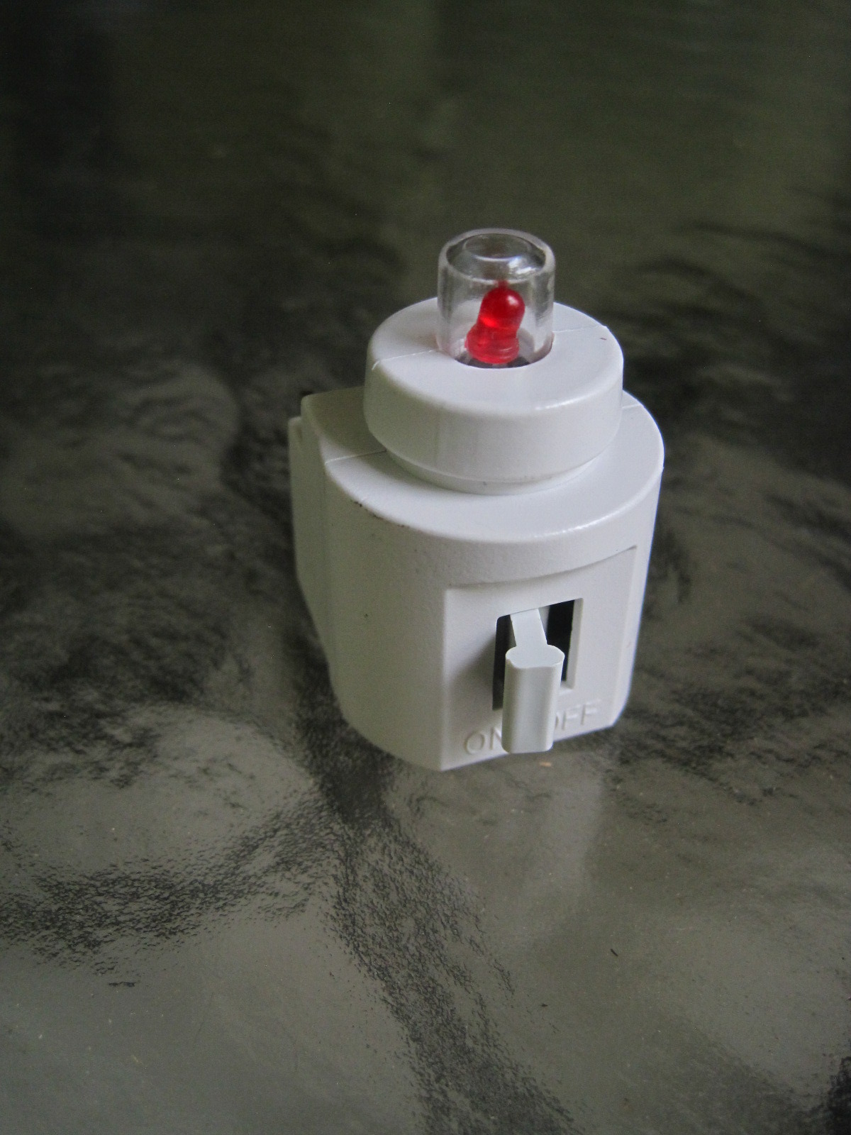
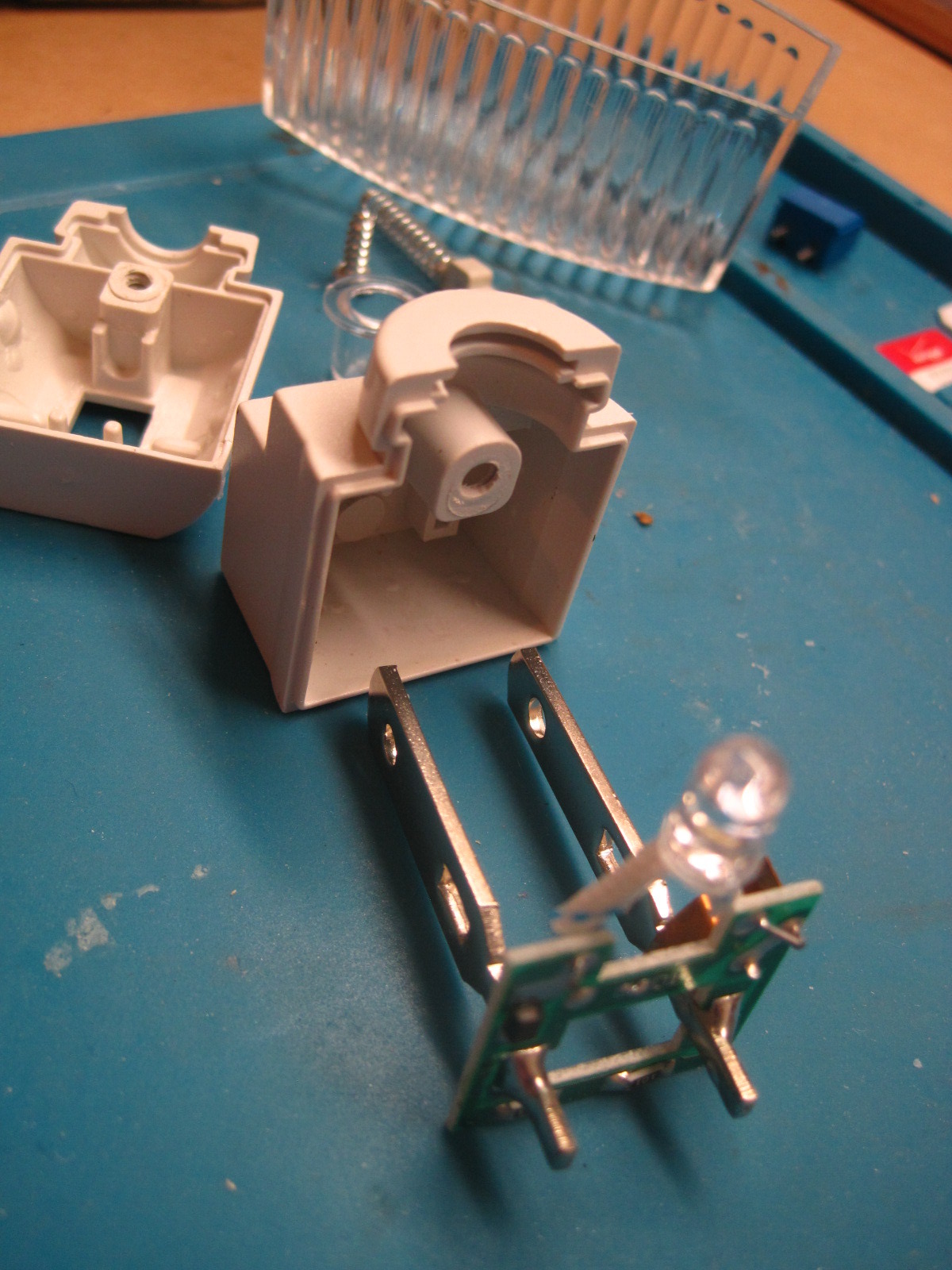
The solenoid used in this safe is shown in Fig. 4, below, where I “exploded” it for a better view.

Fig 4. – Exploded View of Solenoid

Ebay’s safes are generic but the branded ones sold by Harbor-Freight, Amazon, Honeywell and others have virtually identical solenoid mechanisms.

I intended to add a couple of the improvements outlined by YouTube user HifiCentret and YouTube user “Ben J”. I felt that HifiCentret’s improvements would elevate this safe’s usefulness.  However, once I discovered significant deficiency I stopped. The metallic looking plastic opening lever actuator (T-Bar) on the front door is a huge security weakness. More on this later in this post.

HifiCentret adds a cowling surrounding the reset button [see video location 3:17]. This only matters if the rear is accessible and since I intended to mount the safe flush to a wall, secured into the wall and sturdy shelving below, so I am not implementing the cowling.
HifiCentret cut a groove around the solenoid’s shaft to catch the bolt assembly during a “bounce open” attempt [4:15]. I have not yet done this, but I may because it is a feasible, reasonable solution.
HifiCentret reduced the gap between the solenoid and the bolt assembly. I have done this and, in my subsequent tests, I feel that it greatly hampers a “bounce open” attempt.[4:50]
HifiCentret strengthened the solenoid spring by stretching it. I have done this and feel that it is effective[5:30]
HifiCentret installed a physical barrier to prevent someone from puncturing the leftmost LED hole and inserting a wire for snaking over to the solenoid to push it down.[5:50] I did not install HifiCentret’s barrier because (1) I am only trying to protect against basically honest people that visit my home who would not deliberately deface the safe, or anything else in my home; (2) I discovered a far more egregious defect that can be exploited by a person that doesn’t mind deliberately defacing the safe, which I’ll discuss next.

The opening lever actuator (T-Bar) of my safe is totally made of plastic, including the shaft that extends into the safe’s cavity. See Fig 5, below. It is secured by a cotter pin. See Fig 6, below. Plastic may have been sufficient if the shaft that penetrated into the safe’s interior was within a steel tube but in my case the plastic shaft passes through a “pinky finger” size hole in the front plate with no protection inside.  “Ben J’s” safe appears to have [1:48] a desirable steel opening lever actuator (T-Bar) with a short shaft. All of the current products that I see advertised today look identical to mine so, possibly, “Ben J’s” safe is of a different vintage or costlier design. Anyway, the flimsy plastic opening lever (T-Bar) on my safe would be easily snapped off with a stout screwdriver. Then, using the same screwdriver, the remaining plastic shaft could be pushed in, leaving a “pinky finger” size hole that would permit a “pinky finger” or tool (how about the same screwdriver) to press down the solenoid. See Figs. 6, 7 and 8, below. The absence of the steel tube surrounding the T-Bar’s shaft and the parts being made of plastic, makes this safe easy to be defeated by anyone willing to deliberately deface and damage the safe. I  consider this safe to be only slightly better than a locked wooden desk drawer – or possibly of a comparable level of security.

Fig 5. – Actuator Handle (T-Bar)

Fig. 6 Actuator Shaft Inside View

Fig. 7 – Actuator shaft Inside View

Fig. 8 - Finger through Large actuator Shaft Hole

Fig. 8 – Finger through Large actuator Shaft Hole

There is more! The metal thicknesses are disappointingly thin.  Actual measurements are shown in the clickable (to enlarge) images below.


pinky

The steel bolts, which are robust looking, are flimsily attached by peening to the bolt slide, which itself is only 1.13mm thich. See Fig. 9, below.

Fig. 9 – Peened Bolt Attachment

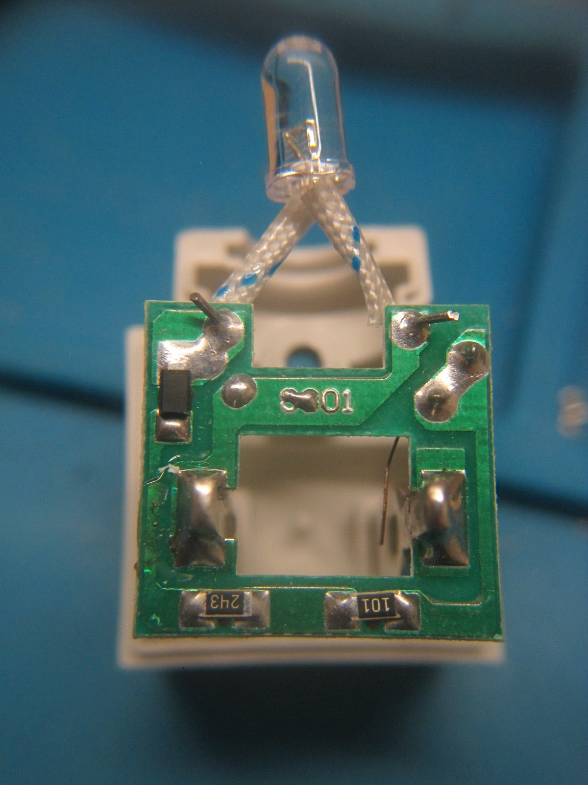
My last figures aren’t a criticism – I’m showing the electronics board for completeness in Figs 10 & 11, below. The PCB is a single-sided Printed Circuit Board that utilizes an ELAN Microelectronics (Taiwan company)  EM78P153S  One-time programmable 8-bit microprocessor.  Fig. 11 is a reverse-engineered schematic of the board. Note – there could be a slight error somewhere in it as it was done rather hastily.

Fig. 10 – Printed Circuit Board (PCB) Front View

Fig. 11 – PCB Schematic

Bottom Line: This safe is useless against a true thief  but may be of some limited value to keep certain items from the eyes and fingers of basically honest people that visit, such as visiting tradesmen, cleaners or house guests.

  1. Credit: Solenoid mechanism diagram is a link to Jaime Capra’s website that reviews “Best Small Gun Safes”.

Posted in Safe, security | Tagged , | Leave a comment

A Good Laser Printer for Linux

A month ago I purchased, via Amazon, a new Brother MFC-L2710DW wireless laser printer/scanner/copier/fax e/w multi-sheet feed and 2-sided printing. Apparently I unknowingly bought it during a big sale because I paid $109 yet the current price is $199. Anyway, it is a great printer that works flawlessly with Linux.  I don’t know why I got 45% off  but if you are interested watch for a sale. You don’t have to pay the MSRP of $199.99 as many websites offer the printer at discounted prices. It is a great printer even if you don’t get 45% off.

I had a perfectly good Brother HL-L2380DW laser printer/scanner/copier/fax BUT it did not do 2-sided copying or have a multi-sheet feeder. It was given to me for free so when my new Brother MFC-L2710DW was delivered by the postman I gave the old HL-L2380DW to him – passing the favor along. He is a beekeeper and needed a printer for his beekeeping workshop.

Brother supplies Linux drivers for all of its printers but, in my case, those drivers are in the Manjaro/arch repository so installation was a breeze on my Manjaro system.
The MFC-L2710DW is much faster than the old HL-L2380DW and I really like it. It handles thicker paper and envelopes easily, as well.
If you need a good Linux-supported laser printer I recommend the Brother MFC-L2710DW

CAVEAT:  The TN760 toner cartridges for the Brother MFC-L2710DW have an embedded Integrated Circuit chip that tracks page count. You’ll see “Don’t buy” warnings from some people because of this. I don’t agree. Personally, I’ve had mixed results with non-OEM toner cartridges but most often I don’t use them primarily because Brother’s toner does not contain fuser oil like most, if not all 3rd part cartridges and toner with fuser oil works poorly for making heat transfer printed circuit board masks. Admittedly, there are new “no heat toner transfer” methods that I have not yet tried and they may work with fuser oil present. If you want to avoid the OEM cartridges just search YouTube for “replace chip of TN760 toner cartridge”. EBay even sells 3rd party TN760 chips in bulk.

BTW: This is an unsolicited endorsement. I have no relationship with Brother – I just like their products and especially their good Linux support.


Posted in Linux | Tagged , , , | Leave a comment

GeoCoin – My 2nd Electronic geocoin

This is my second electronic GeoCoin using the same electronic design. My first geocoin was one shaped like the state of Florida – see THIS-LINK. This one is in a more traditional geocoin shape. The only thing that it does is blink and LED on the top of the board. It should blink for a minimum of a year using a three volt coin cell. I have it blinking once per minute but the rate can be varied by changing the value of R4 and/or C1 which can be seen in the schematic, which is shown in the video.

This was a prototype and design defects will mandate another version. The diameter is too small to accommodate a larger space to write the tracking number. I may be able to scratch in a tracking number on this board ‘s small space with a sharp point BUT it would be difficult. This is a work in progress. A slow work.

Posted in EDA, Electronics, geocaching, hardware, PCB Design | Tagged , , , , , | Leave a comment