UPDATE: In addition to this post, there is also a more recent one titled “A Revisit of the PT2262 PT2272 with Arduino and r06a Receiver” If you find value in this post I believe that you will also like the newer post.
——————————————————-
There is an interesting pair of complementary Integrated Circuits, PT2262/PT2272 that make basic wireless remote control rather easy to implement. They are commonly used in inexpensive wireless devices to control garage doors, fans, toys and even some alarm systems. These ICs utilize fixed address codes and no inherent encryption so they are not high security devices but are maybe about as secure as the average home’s inexpensive door lock.
There are several iterations of these chips sold under slightly varying names with PT2262/PT2272 and SC2262/SC2272 being the most common. The PT2262/PT2272 version is manufactured by Princeton Technology Corp. of Taipei , Taiwan, while the SC2262/SC2272 is manufactured by SilvanChip Electronics Tech.Co.,Ltd. of Shenzhen,China. Both are identical although the Princeton chips are more common and better documented.

SC2272M4 – 4 latched data bits
There are several versions of these chips, identified by different suffixes, that pass through different amounts of data (2 to 6) or even no data at all, as well as latched or momentary data presentation. For example, the PT2272-L4 presents 4 bits of data passed from the PT2262 as latched data with a “VT” pin being a leading edge positive going strobe. The 4 data bits remain latched in their last state. On the other hand, the PT2272-M4 presents momentary data. The more data that is presented, the fewer address leads there are. Each address lead is tri-state – high, low or floating. With a maximum of 12 address leads a PT-2262 provides 531,441 unique device addresses (3^12). On the other hand, the commonly used PT2262-L4, with 4 data bits, only provides 6,561 (3^8) unique device addresses. Addressing is often implemented with solder pads but, occasionally with jumpers and rarely with tri-state dip switches – see images below.

2262/2272 Addressing – solder pads & jumpers

Typical Tri-State DIP Switch
In addition to the addresses there is a resistor in both the 2262 and 2272 that controls an internal oscillator that controls the pulse width of the amplitude modulation and these resistors must be set to complementary values (listed in Princeton’s documentation). For example, if the 2262 uses a 4.7MΩ resistor, then the mating 2272 must use a 820kΩ resistor. The three most commonly used values are 1.5, 3.3 and 4.7MΩ.
The title of this post indicates an Arduino compatible solution that uses this integrated circuit. I recently purchased an inexpensive, Chinese-made 433MHz super-regenerative receiver that utilizes an SC2272-T4, shown in Figure 3, below, which comes with a mated key-chain fob encoder control, shown in Figure 4, below. The transmitter/receiver set that I am using are encoded (A7-toA0) FFLHHHLF and use 4.7MΩ (Xmit osc) 820k (Rx osc).
This set cost me $7US. The Chinese domestic retail price for the receiver is 9 Yuan (about $1.42) and the keyfob is 10 Yuan (about $1.57). The SC2272-T4 is a toggle version of the 2272 that toggles its data outputs rather than presenting the state of the 2262 data bits. Only SilvanChip makes the toggle version of the 2272. This same R06A is also available with the momentary (M) or latched (L) versions yet, ironically, the board designation of R06A remains the same. The schematic of a 315MHz version of this receiver/decoder is shown in Figure 6, below. Amazingly, as this was written, Alibaba.com indicates that the typical price for the R06A receiver module is only 75 to 80 cents each in quantity 300 lots.

Fig. 3: 433MHz 2272 Receiver

Fig. 4: 433 MHz Keychain fob
This particular keychain fob uses a PT2264 instead of a PT2262 but they are functionally equivalent. See Figure 5, below.

Fig 5: Keyfob Inside

Fig 6: Receiver Schematic
The PT2262 encoder sends out a serial string with a sync pulse and then data represented by pulse-width modulation, repeated four times. The PT2272 must match the addresses in two pulse trains to its own address, to accept. One bit is represented by 32 clock cycles. Refer to Figure 7, below to see the pulse widths that represent each value. During the 32 clock cycles two short duration pulses high represent a data bit “0”, two long duration high pulses represent a data bit “1” and one short short duration pulse high followed by one short long duration pulse high represent a floating bit, “F”. Note that the “F” bit is only used in address bits. The leading sync pulse is 4 cycles high followed by low 124 cycles, for a total of 128 cycles. Thus, one individual twelve bit packet is 512 clock cycles long and the 2262 IC sends four repeats. One clock cycle is typically about 300 to 500 microseconds (~451 with my fob). The bit arrival sequence is A0, A1, A2, A3, A4, A5, A6, A7, D3, D2, D1, D0, SYNC.
If you would like to read some C source code that simulates all of this, take a look at the RC-SWITCH project. I compiled the test code “ReceiveDemo_Advanced.pde” and set up the breadboard with the simple ZABR1-1 433MHz receiver shown in Figure 10. When I press the keychain-fob’s “A” key, the output is:
Decimal: 5227968 (24Bit) Binary: 010011111100010111000000 Tri-State: F01110FF1000 PulseLength: 451 microseconds Protocol: 1 (plus the raw data)
When I paste the raw data into Sui’s RC-SWITCH visualization tool at http://test.sui.li/oszi/ the waveform in Figure 7A is the result. If you decode it you’ll see that it matches “F01110FF1000”. Pressing the “B” key yields “F01110FF0100”, the “C” key “F01110FF0010” and the “D” key “F01110FF0001”. You can clearly see that the least significant digits are the data field with the “D” key being the least significant. The address field is “F01110FF” which, if you’ll refer back to Figure 5 and look at the solder pads on the right-side image, you’ll see that the solder address encoding is, in fact, “F01110FF”. Note: remember that the solder pads are backwards – right to left – from the received address “F01110FF”.

Fig 7: PT2262 Encoding per manual

Fig 7A: Captured Waveform of the Keychain Fob (click to enlarge)
Bertrik Sikken’ web page entry, 433 MHz projects, shows a captured waveform of a 2262 transmission with its 4 repeats. See Figure 8, below.

Figure 8: PT2262 Waveform
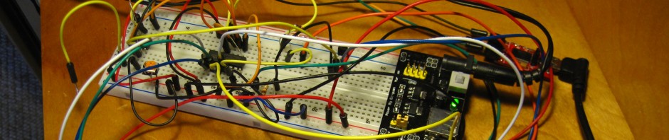
I wrote a short test program for the R06A SC2272-T4 receiver and associated AK-TF04 keychain FOB using an Arduino NANO. The physical test arrangement is shown in Figure 9, below. A YouTube video of my test is at the link below. Note that the video was made using an earlier version of my test code that didn’t use interrupts. In my newer, interrupt driven version, shown below, the VT pin is not polled and displayed because it is, instead, used as the interrupt trigger for a rising edge external interrupt.

Figure 9: R06A Arduino Test Setup
Watch the test video on YouTube.
The source code is posted on PasteBin and may be freely downloaded for your use.

Fig. 10: ZABR1-1 433MHz Receiver

Fig. 11: r06a test schematic
UPDATE: I recently came across another blog with an interesting article about a similar circuit that uses a different integrated circuit – the LP801B/LP802B
See: KaKu-Extend

HI, nice job.
I have the same hardware and I’m trying to use an Arduino to modulate the buttons on the trasmitter to send a codified pattern to receive and decode at the receiver output ports. I don’t know the frequency rate that the transmitter could it support. Another question is how to transform the On-Off behaviour in momentary behaviour.
I hope you have some suggestion to help me.
Regards
Paolo
(sry for my Eng)
LikeLike
I’m not quite sure of your question. It seems that you want to know the maximum rate that you can transmit data frames. If so, then the data rate is a factor of the clock frequency. See page 8 of http://www.princeton.com.tw/Portals/0/Product/PT2262_5.pdf
LikeLike
I’d like to know ho to get more range from the key FOB. At this point it is only about 6 inches.
LikeLike
Your receiver was delivered without an antenna. Mine certainly lacked an antenna when delivered. You must solder on an antenna wire. Notice the copper colored coiled wire that is visible in my photo. For a 1/4-wavelength antenna at 433MHz, this would be 6.5 inches.
LikeLike
There is an antenna on the PCB already. It was coiled up. I have tried it coiled and as a straight wire. It is about 11 inches long. Does nto seem to matter if it is coiled or straight.
LikeLike
I suspect that your unit has a problem – I can use mine well over 50 feet, maybe more (range not really tested). Since you do have a receiver antenna, either the transmitter or receiver may be tuned slightly off frequency or otherwise defective. You may want to open up the fob and verify that its antenna has a good connection, is not shorted, etc.
LikeLike
I had the same problem, I resolved it by feeding it from the arduino instead of directly from the battery. Line of sight range was tested up to 50 meters with transmitter antenna fully extended, maybe it goes further still…
LikeLike
Hi
Thanks for your great post.
I have a question about the latched version of the decoder. What does it mean?
I would need to find a cheap wireless relay which is not toggle or momentary.
To be controlled by the MCU, we would need one key for relay on, another key for relay off.
Do you know if that exists?
LikeLike
When strobed, the PT2272-L chip will “latch” or retain the state of the data bits at the time of the strobe (VT) even after the strobe is over. When strobed, a momentary PT2272-M will activate the data outputs to represent the received data state ONLY for the duration of the strobe (VT). If I understand your application you want a remote relay to be controlled by a microcontroller (MCU) over wireless. You want the relay to be wirelessly operated or released via commands from the MCU. If I understand you correctly, you want the relay to stay in the desired state until it receives another command to change states. If my assumption is correct, then what I would build a relay board with a wireless receiver that used a PT2272-L (latching) chip. So, assuming that data bit 1 is the relay control, sending a data “1” would energize (operate) the relay, while sending a data “0” would deenergize (release) the relay. I think that this accomplishes what you want because, with my fob, pressing the “D” key sets data bit 1 high, which, if connected to the relay, would operate the relay. Pressing any other key (A,B, or C) would drive data bit 1 low, releasing the relay.
On eBay, http://tinyurl.com/wirelessrelay is an example that may do what you want. search for “wireless remote control relay”
LikeLike
I understand you idea.
Looking at ebay sellers, they have different terms for such features like :
toggle: self-locking
latch: interlock
momentary: no locking
I think one of them explains this behaviour:
press A > relay A on and all other off
press B > relay B on and all other off
however, (but I’m not sure about this, as I can’t find the item description anymore)
press B again > relay B toggle
This feature is useful if you want to control window rolling shutters.
Could you please confirm or infirm this?
LikeLike
The Chinese version of English is difficult to understand. However, there are only three possible modes – (1) momentary; (2) latched and (3) toggle, The eBay seller seems to indicate that the device can be set to three different modes so it appears that you can select to whichever works best for you. Check the links in the earlier posts – I fixed them.
For rolling shutters, to me at least, momentary would seem the best mode – active only while the button is pressed.
LikeLike
I have bought the same decoder/fob from Ebay and next step is to build your Arduino test setup which is quite neat… but I have just found a new device that decodes all those chipsets into a serial stream. Look at this
http://www.ebay.com/itm/281018216488?ssPageName=STRK:MEWAX:IT&_trksid=p3984.m1438.l2649
You can use it to decode or intercept all sorts of 433mhz devices (weather stations etc). Though I am a total Arduino newbie, if you know of a similar project that can filter/display a uart serial stream of data, appreciate any advice.
LikeLike
There is a similar and less expensive solution – the NT-T02B transmitter ZABR1 receiver set. I paid $5.49US including delivery. I wrote about my tests on the Arduino forum but not on this blog. Maybe I’ll do some more tests and post a report on this blog. If you want to read my Arduino forum post it is at: http://arduino.cc/forum/index.php?topic=88132.0
LikeLike
hi, link please, missing from above.
btw – is there a way to say capture and log say data from 2272/pir sensors from ebay and display on arduino lcd which sensor transmitted. like a mini log of last 4 pir 433mhz detections. Am unfamiliar with logging and dislaying (or even scrolling) a small log on arduino lcd. that would be cool.
LikeLike
Link corrected
LikeLike
Do you have a schematic of how you connected 2272 to which arduino pins and lcd and receiver wiring? I am a complete newbie sorry. Really want to log the 2272 wireless detections and maybe ad a real time clock to log time too.. like this one
http://www.ebay.com/itm/1PCS-I2C-RTC-DS1307-AT24C32-Real-Time-Clock-Module-for-arduino-AVR-PIC-51-ARM-/370733928915?pt=LH_DefaultDomain_0&hash=item565176d1d3
LikeLike
I just posted a schematic of my test circuit as Figure 11.
LikeLike
Unless power loss is a big concern, why not just use software timing? See: http://playground.arduino.cc/Code/DateTime
LikeLike
thanks for fig 11, appreciate it and for datetime idea, no need for dallas rtc/batt .
The arduino has 512k of internal memory which would be ample for logging the last say 10 detected events. Any references or ideas to recording and displaying past events on the lcd from its 512k memory would be interesting (without going to sd cards or using a laptop).
LikeLike
btw – just got my Ro6a from Ebay today. I see on the back of it it has an 8 pin surface mount chip, (lm380? cant read numbers) that would be an op amp. Any idea what that is doing? I want to run the arduino and R06a from batteries – always on. Need to measure how much current r06a and arduino is drawing.
Another question (sorry for my enthusiasm) – for numerous sensor detection (>4) with a single r06a I would need to detect say 2 simultaneous highs that would identify the transmitter. ie 1010 then pir1 high
how do I change code to a conditional ie
if r06a_0 and r06a_2 is High then lcd.print “pir1 high”
thanks
LikeLike
I examined the chip on the back of my R06A. It is labeled “358 GZ208 or 358 6Z08”. The schematic in figure 6 shows that it is an LM358. I can find no IC matching these markings. In any case, your real concern is the current draw. I have not measured it but the R06A’s specifications state “Working current: ≤3.0mA” If you are using an Arduino board, then arduino.cc will list the current draw per port. Quiescent operation of a Arduino Duemilanove is reported as 18.7 mA. Add to that additional current sourced by active ports. I suspect that an Arduino mini will have the lowest current draw. To accurately determine your power supply needs you will need to put an ammeter in series with the power supply to your project.
——————–
if(r06a_0==0 && r06a_2==1){
lcd.print “pir1 high”;
}
———–OR——-
r06a_data = (r06a_0 | r06a_1 << 1 | r06a_2 << 2 | r06a_3 << 3);
lcd.print “Transmitter ”;
lcd print r06a_data;
lcd.print “ detected”;
switch(r06a_data){
case 0:
/* put appropriate task code here */
break;
case 1:
/* put appropriate task code here */
break;
case 2:
/* put appropriate task code here */
break;
case 3:
/* put appropriate task code here */
break;
case 4:
/* put appropriate task code here */
break;
case 5:
/* put appropriate task code here */
break;
case 6:
/* put appropriate task code here */
break;
case 7:
/* put appropriate task code here */
break;
case 8:
/* put appropriate task code here */
break;
case 9:
/* put appropriate task code here */
break;
case 10:
/* put appropriate task code here */
break;
case 11:
/* put appropriate task code here */
break;
case 12:
/* put appropriate task code here */
break;
case 13:
/* put appropriate task code here */
break;
case 14:
/* put appropriate task code here */
break;
case 15:
/* put appropriate task code here */
break;
default:
lcd.print “ERROR:Should not reach here”;
}
LikeLike
From what I understand, this is a big limitation when using the hardware decoder, as the decoder is setup for a single address.
If you want to handle multiple sensors with multiple addresses, you need the rcswitch software version.
LikeLike
thanks for the tips everyone. I will look into rcswitch libraries for decoding diff addresses – would save a little current doing it that way too.. The power led on my arduino uno board is drawing most of the current, will have to desolder it. Also need to figure out how much power the usb interface is wasting.
If anyone has some links/clues perhaps easy libraries way (I am new to programming) to storing events in EEPROM (rx event plus timestamp) and recalling on the lcd, appreciated
LikeLike
Where did you find this transmitter receiver?
LikeLike
On ebay from a Chinese vendor
LikeLike
http://dx.com/p/4-key-wireless-rf-module-w-remote-controller-152284
🙂
LikeLike
Pingback: TÉCNICA – Conserto de controle remoto de portão eletrônico | Dicas do Zébio
How does the reciever identify the transmitter, in other words if I had another 433 MHz Keychain fob would this receiver decode that signal? or is there a pairing mechanism ? if so can you please elaborate, Thanks !
LikeLike
Look back at the post – The receiver has its address hard-coded/hard-wired into it. The transmitter sends out a 12 digit sequence, like this “A0, A1, A2, A3, A4, A5, A6, A7, D3, D2, D1, D0, SYNC”. All in-range devices receive the message but only the device whose address matches A0-7 will accept the data digits, D0-3 and present them as valid output. There are different versions that configure the 12 digits differently with more or less address or data bits. Fewer address bits more data, less address bits, less data. Eight address digits and Four data digits is the most common.
The chip set presented in the post has its address hard-wired but there are software receiver versions (not discussed in post) that include “training” the receiver to learn its code, such as transmitting the desired code while a receiver button is depressed. for example.
LikeLike
So this mean only one transmitter can work with this receiver (which is pre hard coded) ? and receiver which have the learning code feature can support multiple transmitters ?
Thanks for the quick response ::)
LikeLike
Only one transmitter at a time. Since it is a single frequency multiple transmitters sending simultaneous bursts would collide and corrupt each other. One method of using multiple transmitters would be to design and implement a collision avoidance scheme similar to Carrier sense multiple access with collision detection (CSMA/CD) utilized in Ethernet. I know of no commercially available transmitters e/w CSMA/CD so this would be a DIY project. Since this chip set is all about economy it probably isn’t the best choice for CSMA/CD.
LikeLike
i want to make wireless automatic home door without using integrated circuits??plz tell how i make it???circuit diagram???block diagram???
LikeLike
In eBay search for “Diy Rfid Door Control Kit Electric Strike Lock”
LikeLike
by any chance have you done any range testing with these?
LikeLike
Only in the most casual fashion. Without extending the pull-out antenna I tested it 50 feet away within my home, through multiple walls. I suspect, but have not tested, that extending the antenna would enable 100 or more feet and maybe further with a clear line-of-sight.
LikeLike
First I tried that product, I connected LED to D0, and tried it. It was quite good in 1 meter distance, but LED wasn’t working well for more than 1 meter. It was not stable for more than 1 meter. It was bright for less than 1 meter ,but after 1 meter it was blinking. I spend a whole day on forums and I found the solution for that problem. Problem is power source. First I tried a USB port on my laptop and Arduino 5V output but both of them caused that blinking problem. After that I tried my mobile phone charger ( which can supply 5V and up to 1.8 A) . It was not blinking no more. I did tried it for 5 meters and it was ok. But it will likely work more than that range.
LikeLike
But be careful about external power supplies. Some 5V chargers’ outputs are 5.5V and they brokes your receiver . For ex. 5V is written on my camera charger and when I connected a voltmeter to it’s output, it was 5.5V . I damaged my first receiver while using that power supply.
LikeLike
hola yo compre en ebay un receptor que tiene el sc2272 con dos reles, y lo quiero instalar en un porton automatico y necesito generar un pulso para desactivar el rele que funcione con los limites.
LikeLike
Hi – can you tell me where you get the graph of picture Fig 7A ?
LikeLike
As per the post “When I paste the raw data into Sui’s RC-SWITCH visualization tool at http://test.sui.li/oszi/ the waveform in Figure 7A “
LikeLike
Dear Celem,
I see that you know the ins and outs of these transmitter receiver units. I purchased a one button remote. The relay energizes immediately upon pushing the trans button, but there is a 1+ second delay after releasing the button until the relay drops out. Is there any component that would introduce that delay?
…
burt
LikeLike
The delay is probably in the relay device as the RF transmitter send a short burst. The delay is unlikely to be an integrated circuit, unless the relay device is for some sophisticated purpose. Most likely you’ll find a driver transistor and a resistor+capacitor circuit that holds the transistor’s base active until the capacitor drains down through the resistor. Such a circuit would exist because the RF pulse is too brief to activate the relay. You could easily decrease the value of the resistor to reduce the delay time. The capacitor could also be replaced with a lower value capacitor but it would cost more than a new resistor.
LikeLike
Many thanks for this post,
I’ve learnt many things here, and took me to look at the difference between the two/three M4/L4 or timer receiver différence.
I want to send GPS info thru RF, but so far this module will not work because no data can be sent?
Am I wrong?
If I well understood, I’ll use a M4 receiver version ..
I like dit for the distance, but if no data can be sent, it’s useless.
http://dx.com/p/mtdz004-wireless-transmission-module-black-green-157254#.Uw5aE3-9KSN
Many thanks for your advice and blog
LikeLike
Four bits of data can be sent for each strobe of the VT pin. For a GPS location multiple transmissions would be required so you may want to work with a relative position. For example, sent an absolute position once (anchor position), requiring multiple transmissions to send an entire lat/lon, and subsequent single transmissions that represent a delta from the anchor. Doing it this way requires some flag to differentiate a single “delta” transmission from an “anchor” set of transmissions. For example, the first word of an “anchor” set of transmissions could be a unique value, such as 0xF, that indicates that additional packets follow.
Good Luck.
LikeLike
Many thanks for your reply.
I’ll send indeed 3 values:
– AcquisitionTime (hh:mm) or last part of a TimeStamp. (year, month, day are not needed)
– Longitude and Latitude (only the last digits of the GPS position). As long as the RF has a maximum 3km portage, the first digits of the GPS position are useless .
Could you advice me, regarding the Receiver? M4 or L4, I’m finally a bit lost..
LikeLike
M4 or L4 depends on whether you want the data to be latched or not. L4 latches the data upon vt strobe while with M4 the data output’s continuously float with the inputs and you monitor the strobe to capture the data. An L4 might be better for a control loop architure while a L4 would work well with an interrupt architecture. So, choose according to your intended design.
LikeLike
Pingback: 433mhz Wireless Remote Control PT2272 for Arduino (EN) – CI SC2272 para controle Remoto 433mhz (PT-BR) | The most curious of the earth
I have one of these inexpensive Chinese motion detectors which operates wirelessly at 315Mhz. It is similar to this one with the 1527 chipset but they are also available with the 2262 chipset:
http://www.ebay.com/itm/Wireless-Standard-PIR-Motion-Detector-Sensor-315-433-Mhz-1-5-3-3-4-7-M-/171089657359?pt=LH_DefaultDomain_0&var=&hash=item27d5bcfe0f
I am trying to receive the signal when motion is detected using the arduino uno. I tried using the MX-05V receiver along with the code found here:
http://www.ebay.com/itm/Wireless-Transmitter-Superregenerative-Receiver-Pair-315MHz-DE4220-/310959069614?pt=LH_DefaultDomain_0&hash=item48669ad9ae
This receiver is not receiving anything when the motion detector is triggered. If this isn’t too far off topic, can you point me in the right direction? Should I get a motion sensor with the 2262 chipset? Do I need a decoder? Perhaps this is too complicated for a novice such as myself?
Just for the record, I want to set up wireless sensors outside my home that will trigger recording on my Blue Iris camera system. Detecting motion via the cameras is too unreliable due to shadows when the wind blows.
Thanks!
LikeLike
When you say that the “receiver is not receiving anything when the motion detector is triggered” have you looked directly at the data output pin of the MX-05V with a scope of pulse detector? Did you put an antenna on the MX-05V (10-15cm)? Are you absolutely sure that it is on the same frequency as the transmitter?
Likewise, how do you know that the transmitter is actually transmitting anything? Have you looked directly at the data output pin (pin 4) of the 1527 chip?
LikeLike
Thanks for the response. What I mean is using the arduino code from the example in my first link, when the motion detector is triggered (pir lights up when it is transmitting), I do not receive any text in the serial monitor nor does the led attached to the arduino’s pin 13 blink. I have tried other people’s mx-05v coding examples without success.
I do not have the equipment to look directly at the data output pin of the mx-05v.
I am not using an antenna because I have the pir a few inches away from the mx-05v, but perhaps that’s not good enough?
I looked inside to verify the PIR uses 315mhz and it does (plus my 315mhz alarm system uses this same pir). For the mx-05v, I am struggling to verify it is tuned to 315. It has 315, 330, 433 printed on the back, but looking at the opposite side, its not obvious to me how I can verify they sold me what they say they sold me (315mhz)
I know the transmitter on the motion detector is transmitting because I tested it on my security system (inexpensive chinese alarm system) that uses these same 315mhz wireless pirs.
I know the alarm system led (which normally blinks when a wireless signal is triggered) didn’t blink when there is motion on this pir until I put the alarm system into learn mode and then triggered the sensor. I assume this was so the alarm system would learn the address of the pir.
LikeLike
Re – “…I know the transmitter on the motion detector is transmitting because I tested it on my security system (inexpensive chinese alarm system) that uses these same 315mhz wireless pirs.
I know the alarm system led (which normally blinks when a wireless signal is triggered) didn’t blink when there is motion on this pir until I put the alarm system into learn mode and then triggered the sensor. I assume this was so the alarm system would learn the address of the pir…” – OK, you have verified that the PIR is/was capable of transmitting AND that it is on 315MHz.
You really need a way to look directly at the data output pin of the mx-05v. Without test equipment you are flying blind. You might, and I emphasize MIGHT, be able to use a d’arsonval movement multimeter (needle – not digital) to detect a dip when the data lead is outputting data. The pulse train may be too quick to detect. You should, at a minimum, get a logic probe. See the link below.
“…I am not using an antenna because I have the pir a few inches away from the mx-05v, but perhaps that’s not good enough?…” It would be best to have some sort of antenna, in my opinion – just a piece of wire 15cm long will do.
Anyway, I re-read your original comment and I feel that your primary problem is that you are using code that won’t work. Your said “I tried using the MX-05V receiver along with the code found here:
(see original comment for link)” That code is for sending ASCII code over the radio/receiver. However, neither the 1527 or 2262 chipsets utilize ASCII and therefore your code will not work. You need to use code designed for the correct protocol. A link for code for the 2262 chip is in the main body of this blog post. Be advised that the 1527 chipset protocol is different and this code is unlikely to work. If your PIR is using a 1527 I recommend that you read the Arduino forum thread at the link below. It contains code that should work AND there are people there that have gotten that chip to work. Good luck!
LOGIC PROBE ON EBAY: http://tinyurl.com/py6ev6n
Arduino 1527 thread: http://forum.arduino.cc/index.php/topic,99714.0.html
LikeLike
I just wanted to add a follow-up. I got this going using the code and library found here:
http://www.wes.id.au/2013/07/decoding-and-sending-433mhz-rf-codes-with-arduino-and-rc-switch/#more-124
A huge thank you to Celem for recognizing that I was using the wrong code, and also letting me know that the hardware I had should work. After taking his advice to find code for the 1527, I am now up and running. Not only can the Arduino now receive sensor data from the 315mhz PIR, but its also able to receive data from the wireless door/window sensors, the glass break sensors, and the four button remote controls that control my alarm system.
Opens up a lot of possibilities.
LikeLike
That is awesome. Thank you so much for pointing me in the right direction.
LikeLike
I did some range testing with this device…
The receiver was placed at my house with the wire on the receiver extended fully. Since this is a receiver, that doesn’t matter (much). There are LEDs on each relay…1 to 4…to indicate that the receiver did/did not receive and latch the button press.
I took the fob up the hill behind my house and managed to trigger the receiver at ~700 feet with a completely unimpeded line-of-sight. The antenna on the fob was fully extended and held in the same plane as the receiver antenna. Four button presses (one each ABCD) resulted in four LEDs on when I got back.
LikeLike
Hi,
i have a this rf module


and i made a buzzer alarm using sensor. you can see it here; http://www.youtube.com/watch?v=5eknbq9X9GU
i want to use this rf module for remote controlled the buzzer alarm circuit.
how can i make power on / power off process to my buzzer alarm or any circuit using this rf module?
is it possible?
sincerely
LikeLike
The simple answer is yes. The data output pins of the receiver will follow the pins pressed on your transmitter fob. However, you will may want the “latched” chip, not the “Momentary” chip, so that your data lead will stay latched low or high depending upon the key selected signal sent by the fob transmitter – for example the pin state could control a relay that controlled a power supply for the buzzer circuit.
LikeLike
Hi
Did you think that I can use your solution with a transmitter based on HS2262?
LikeLike
Hi
Can I use your solution with a HS2262 transmitter?
LikeLike
I would say yes. The specs that I found for the HS2262 state “HS2262A is a low-power CMOS process universal coding circuit, each circuit has a user the flexibility to change the Address code and data codes for the composition, the circuit has a power-saving mode, can be used for radio and infrared remote control transmitter, and PT2262 Compatible“. The specs that I found are in Chinese but running it through Google translate yielded the above translation. See:
LikeLike
Reblogged this on Diário de Nilton Felipe and commented:
Controle Remoto com Arduino
LikeLike
Hi,
Does VT need to be connected to an Arduino pin? I ordered the momentary version with the PT2272-M4 chip. Thanks for this great guide.
LikeLike
Yes. You need connect the VT pin to the Arduino and monitor it, either by polling that pin or by interrupt triggered by the VT transition. Re-read the post and you’ll see that I tested it path ways, with interrupts being, by far, the preferable way. Good luck.
LikeLike
AWESOME write-up. I appreciate your time and expertise that you’ve shared on this topic as I have been researching this particular 2262 chipset myself and greatly appreciate your input on this.
Due to some of my own confusion may I ask a quick question? For my application below would I use the momentary or latch? My guess is latch.
I am helping a high school student complete a “quiz bowl” type game to donate to the debate team. We are using the Arduino mega 2560 for the main mp. I want to use 8 handsets that communicate wirelessly back to the arduino. I thought that if I had hard-coded addressed transmitters in each hand-trigger unit and a matching decoder on the arduino side (each being hardcoded to one another) the arduino could then listen for a “high” to be presented on a given input pin and register the time-ins of each player and rank accordingly.
So basically, I want to have the transmitters send a high at the pressing of a momentary button and have it picked up at the correct decoder and presented as a voltage high to the arduino. I have seen some decoders handle up to 8 of these but I have also seen them done 4 per decoding board.
Which chipset pair would you recommend for that?
LikeLike
Given that your Arduino won’t have enough accessible interrupts to use as my post describes, you’ll need to operate by polling the ports. So, latched mode would help insure that a keypress wouldn’t be missed. However, depending upon the cycle time of your loop you may be able to process momentary keypresses – it all depends upon your application. If you can figure out how to handle eight interrupts you’ll be better off, etc., all VT inputs tie (possibly through diodes) to an interrupt whose interrupt routine then quickly polls all inputs and sets flags for subsequent processing in the main loop. Good luck.
LikeLike
Remember only one handset can send at the same time or they will screw up each others signals. (The share the same media, air.) So using 8 receivers is kind of useless.
LikeLike
Not totally useless – the address stream is repeated four times for just this situation. Yes, a complete obliteration for all four repeats is possible, especially with eight remotes, but, in many, if not most cases it is likely that enough will survive to permit a successful transmission.
LikeLike
Hi,
Thanks for mentioning me in the article! This pointed me to some nice pieces of code to use the remote for more then the default set, thanks! I thought about using it with another LED light and a cheap receiver but didn’t because I had to make the receiving part. Now that’s already there I might add it later.
Timo
LikeLike
Can a SC2272-T4 be set for momentary ?
LikeLike
Sorry, but no. The chip is hard wired for “Toggle” mode. For momentary you need the SC2272-M4 chip.
LikeLike
I’am new to electronics, I have a project I want to build but how do I get someone (like Celem) interested in helping me and answering my dumb questions? The project is remote control auto turnsignals to place on my antique car. I would be glad to send you my email. Tim
LikeLike
consulta..
tengo todo.. pero me falta la bateria de mi llavero (control rf) .. me puede decir que tipo de pila o bateria es la que se usa.???
Gracias
LikeLike
Lo siento. No estoy hablando de competentes españolas y no puedo responder. (used Google Translate)
LikeLike
What you write in GREEN on your schematic is hard to read. I am sure it exists darker colors?
The rest is very good, thank you.
LikeLike
Pingback: Buschtrommel OnlineMagazin » Blog Archive » Singnal von Türkontakt mit PT2264 abfangen
Hi.
I want only let you all know that this little and useful board, can put on the outputs 0, 1, 2, 3 or more HIGH level, due only to the transmitted pattern.
The transmitted pattern can be any number from 0 (included) to 15 (0 to F in Hex).
This is not a conventional way to use the tiny transmitters, but is possible to do it.
In my application the outputs are placed to two couple of motor driver.
For every couple there is forward and reverse drive, so that using this device, the output could be driven contemporary!
For my application this is a potential risk that I have already avoided with a strong “interlock” on the opposite outputs, and also in the screening (and debouncing and filtering to accept only valid inputs, not contradictories.
I think that is important to knows that the capability of 2272 to drive at the same time, more than one single output; this is an interesting thing that can extend the application of the device, and permit to have more informations (16 instead of 4).
But is also important to knows the opposite face of this detail, that without the due precautions, could be turn into problems, big or little.
We can obtain more than a single output contemporary drive, only pushing 2 or 3 or 4 buttons, together into a very close time.
We need to be very quick to pushing the whole “N” buttons on the transmitter, if we want transmit all the “N” binary informations.
If between the pressure of the whole buttons we will not enough quick, only the output corresponding to the FIRST button pushed will be driven ON.
That’s all
LikeLike
Hello
I really love your work..the schematic diagram in figure 11 did you draw using Proteus and if so how can I get the libraries for the RF receiver??..
Thanks
LikeLike
Figure 11 was created by gSchem which is part of the gEDA Open Source software suite for creating printed circuit boards. See:
Re “libraries for the RF receiver” – there are none. All source code is in the PasteBin shown in the post and repeated below:
I use Open Source software almost exclusively. I have only one commercial software package on my Linux desktop and it is finance related, not software/firmware related.
LikeLiked by 1 person
Thanks alot
LikeLike
Hi, nice project.
I have a little problem with my implementation of PT2272.
I changed a bit your code (deleted lcd stuff etc.)
In the void loop,
when i toggle pin 13 (led) it works fine,
but when I change it to let’s say pin 4 (where I have connected a relay) i doesn’t work like planned
(when i keep button pressed the relay goes ON and OFF and ON…)
Any idea what is wrong?
Best Regards,
Michal
#define PIN_D2_INT 0
// R06A defines – wired to Digital Arduino pins
// Wire the R06A per this assignment
#define R06A_VT 2 // used for INT0
#define R06A_D0 3
#define Led 4
int r06a_0 = 0; // storage for data states
int dirty = 0; // interrupt has occurred flag
// Interrupt Service Routine attached to INT0 vector
void pinD2ISR()
{
// Provide a visual clue of the interrupt
// Grab the data states
r06a_0 = digitalRead(R06A_D0); // Grab data for later consumption in loop()
dirty = 1; // flag interrupt occurance
}
void setup()
{
Serial.begin(9600);
attachInterrupt(PIN_D2_INT, pinD2ISR, RISING); // Set D2 interrupt
pinMode(R06A_D0, INPUT);
pinMode(Led, OUTPUT);
}
void loop()
{
if(dirty)
{
dirty = 0; // clear interrupt occurance flag
digitalWrite(Led, !digitalRead(Led)); // Toggle LED on pin 13
Serial.print(“state = “);
Serial.println(“pressed”);
}
}
LikeLike
Look at:
void loop()
{
…
digitalWrite(Led, !digitalRead(Led)); // Toggle LED on pin 13
…
}
The code is specifically written to toggle the LED, or in your case, a relay, which will cause it to turn on and off in sync with R0ra’s VT lead. Regardless of how long you press the button, the VT is only a pulse and you are apparently causing multiple pulses on the VT by holding it down, which in turn fires multiple interrupts and multiple toggles on the Led/relay pin.
Something like the following may work better for your application – operating the relay to the state of the r06a data bit 0 just read:
…
digitalWrite(Led, r06a_0); // Operate relay to state of r06a data bit 0
…
LikeLike
well,
(I use only one-always the same button on the pilot,S1 button)
if i write: (for LED)
digitalWrite(13, !digitalRead(13));
it works as I want, but if i write (Pin4=relay)
digitalWrite(4, !digitalRead(4));
it switches On&off&…
isn’t it weird?
should work exactly the same?
LikeLike
Michal, The statement “digitalWrite(4, !digitalRead(4));” reads port D4 and then inverts the value “!”. Thus, if D4 is HIGH, because +5V is being applied to the relay via D4, then a HIGH will be read from D4, then inverted by the “!” to a LOW and output by the digitalWrite to D4, forcing it low, which de-energizes the relay. As written, it will, by design, switch the relay on and off. This is why I suggested that you instead use “digitalWrite(Led, r06a_0)”
LikeLike
different version of code (setup void is ignore here)
this one works
const int Usb1 = 13; // the number of the LED pin
this one doesn’t
const int Usb1 = 4; // the number of the relay
CODE:
void loop() {
noInterrupts();
StateCopy=state;
interrupts();
digitalWrite(Usb1, StateCopy);
delay(10);
}
void blink() {
state=!state;
}
LikeLike
Hi.
I have had a problem very similar to your.
The highest bits were been transferred, while the lowest remains as dead, or blind.
Before to enter in the listing of your program, I suggest you to control the voltage across the PT2262 and PT2272, because if the voltage decrease (as in my case) the frequency of OSC slow down enough to have this strange kind of behavior.
Let’s try.
LikeLike
I realized that it works fine from the distance not more than 1cm ? 😦
LikeLike
Have you installed an antenna on the r06a? If your radio is 433MHz, then the optimal 433MHz ¼ wavelength antenna is 173mm. Without an antenna your radio’s performance will be poor.
Look at the brown wire antenna that I put on my r06a:

LikeLike
yes I have an antenna. but i still dont know why led works up to 3meters and relay switches on/off. I used external usb power supply and still the same
LikeLike
Try putting your complete source into a PasteBin and post the link here. An explanation of what you are trying to acomplish would be hlpful as well as a link to a photo of your setup. There is too much unknown for me to comment further.
LikeLike
I want to build a “wireless button”. Pressed once It should switch on a LED/Relay, pressed for the second time it should switch the LED/Relay off.
I have a set:
1) YK04, PT2272-M4 (momentary; receiver)
+
2) JY-02 PT2262(rc; 4 buttons)
(315MHz)
I use arduino Uno and relay shield v2.0
http://www.seeedstudio.com/wiki/Relay_Shield_V2.0
I have just found a simple code for implementation:
http://pastebin.com/ChN8R5JS
as outputs i use 3 Relays and 1 LED
the code above works like this (doesn’t use Int0, just normal loop):
(distance 1meter):
When I press buttons 1-3 (button held pressed-down) (to switch the relays on) the relays switch On/Off/On with freq I would say 5Hz (I can hear the relay and see the blinking led from the relay shield), when I release the button the relay stays OFF.
When I press button 4 (to switch the LED on) it switches ON the led (when the button is pressed-held down), the led goes off when I release the button (I cant see blinking; I dont have an oscilloscope to check).
(distance 1cm) it works fine (both relays and led; relay stays on when the button is pressed and off when released).
LikeLike
Based on what you wrote, the transmitter is a momentary output type (The PT2264 chip is available in both momentary and latched). Your pastebin code is ignoring the VT pin and only monitors the data pins for HIGH or LOW. For what you are doing this is a viable approach.
The code looks like should work as desired. Given your issue of having to be one centimeter away you seem to have a hardware issue, not a code issue.
At one meter you appear to be having decoding errors which is probably manifesting itself as undesired changes in the data bits and thus issues with the relays. The LED may also have issues but the human eye may not be able to detect it if the state is changing fast enough. At one centimeter the RF signal is being correctly detected and decoded, resulting in correct operation.
Try adding some delay() in the loop() to slow things down and see if you can see something more obvious.
In my opinion, you have problems with either your RF transmitter or receiver or both. The frequency tuning may be off at either end or both; there may be interference from somewhere else in the room or even RF noise from the relay board, the Uno or something else nearby, sufficient to swamp the receiver. Do you have another receiver/transmitter that you can substitute to see if it works? If not, try tenting some aluminum foil around the relay box to shield noise that may be coming from there.
My bottom line – most likely cause – the radios are at the center of your problem. Try a different radio set.
LikeLike
photo
http://i.imgur.com/vUszIAB.jpg?1
LikeLike
i have another receiver and transmitter and it is exactly the same
LikeLike
with the previous code (Int0) it was ok when I used FALLING edge
LikeLike
Try the following to see it helps you see what is happening. I still feel that it is hardware, not software.
——————
void setup()
{
Serial.begin(57600);
…
void loop()
{
// Read the state of the first input value:
readState = digitalRead(inputA);
if (readState == HIGH) {
// turn LED on:
digitalWrite(outputW, HIGH);
Serial.println(“digitalWrite(outputW, HIGH);”);
}
else {
// turn LED off:
digitalWrite(outputW, LOW);
Serial.println(“digitalWrite(outputW, LOW);”);
}
…
// at bottom of loop
delay(1000);
}
}
LikeLike
Try:
LikeLike
Looking at your sketch, I seem that the relay can be Powered or not, depending by the “LAST” condition of the switch.
As all we knows, the bounces can do some unknowable behavior.
The delay at the end, cannot resolve the problem of the bounces.
You have to read the state of the switch for a considerable number of mS.
Meanwhile, if the state change, you have to restart the time and the count.
You have to drive the relay (ON or OFF) only when the state of the pushbutton under constant control, still stable for the defined time.
LikeLike
Contact bounce won’t be an issue since you are looking at the output of the 2262, nor should the relay be a problem other than possibly generating RF noise. The purpose of the delay is only to slow things down to a speed more humanly observable. It was not expected to cure your problem. The serial output should prove useful for debugging.
LikeLike
It look that delay helped.
I went back to the Int0 version below.
It looks like delay(xxx) works like a range setting.
delay(400) range ~1m
delay(1000) range ~3.5m
any chance to reduce delay?
void loop() {
noInterrupts();
StateCopy=state;
ic=i;
interrupts();
Serial.print(“state = “);
Serial.println(ic);
digitalWrite(Usb1, StateCopy);
delay(400);
}
void blink() {
state=!state;
i=i+1;
//buttonState1 = digitalRead(button1Pin);
}
LikeLike
Re “It look that delay helped”
The delay() should not help anything. Its only purpose was to slow things down so that you could better observe what was happening – for diagnostic purposes. The delay(1000); causes a 1,000 millisecond delay – one second. If you are seeing delays of minutes (I assume that “delay(1000) range ~3.5m” means 3.5 minutes?) then the delay(1000) is not causing it other than it may be masking some data pin state changes that occurred during the delay. At this point, I recommend removing the delay() as it is only masking the problem. Use the Serial.print() as a diagnostic!
I suspect that if you will monitor the Serial.print() output that you will discover a lot of unexpected data bit changes coming in over the radio, which is probably what is causing your problems.
You do not have a contact bounce problem, at least on the rf receiver end. The output of the PT2262 chip is a clean electronic level change. I can’t tell what you have on the “JY-02 PT2262” end – looks like a single pushbutton switch. You “might” have debounce issues there, although it is hard to imagine it causing what you are seeing. Anyway, you could try a simple debounce circuit on that pushbutton switch, if not already present under that red plastic (3D printed?). A 10k resistor and 100uf capacitor is all that is needed – wired this way = Circuit Debounce
I still believe that you have a hardware or interference issue in the radio area. Use the Serial.print as a diagnostic. The fact that moving the radios together closer solves your problem proves this as the culprit. I can use mine well over 50 feet, maybe more (maximum range not really tested)
LikeLike
In any case this program “catch” continuously into the length of the time, just random informations about the state of the output in that moments. My opinion is that this way it’s not the better one for a toggle mode.
LikeLike
any suggestions how to do it better ?
LikeLike
Oh, yes:
void NoBounce ()
{
if (PB != PBhist) // All the changes …..
{
FrzTime = millis(); // will Freeze the time of the event.
}
if ((millis() – FrzTime) > DefTime)
{ // if the defined minimum time is over, the data is assumed as stable
if ((PB != PB) && (PB == OFF)) // Is it a New command ?
{
CmdNew = 1; // There is a new command (ignore the release of PB)
}
}
PBhist = PB; // In any case keep the current state for later
}
Note: CmdNew its to be cleared by the part of the program that handle the command.
In my application new commands are not accepted until CmdNew still to 1.
This probably don’t resolve your problem, but I feel to recommend you this kind of precaution in all the cases where there are event with unpredictable behavior.
Using the couple PT2262 and PT2272, the “bounces” properly named don’t exist, but remains the cases when the command cover more than one single output. This property can be welcome or damned it depends by the kind of application.
What to do in these cases?
In my case I have to move some motor forward or backward (up and down), so I cannot permit contemporary output. I prefer start killing multiple input, and at the end, verifying that one output only it’s ready to be driven. My sketch include many heavy screening part, hoping that will remain excessive scruples.
LikeLike
A debouce circuit as the one suggested by celem, can surely help, reducing all the unwanted transitions of the state readable from the switch, but only the many transitions far from the threshold voltage of the electronic input (the uC I suppose).
The transitions closely around the threshold of the input will be reduced (much) in amplitude, but not as number. So this example is to be followed from a Shmitt trigger input as 74HC14 or similar.
You can also verify if the inputs of the uC that you are using has this hysteresis characteristic.
Furthermore a circuit like that, is welcome using one switch, but became wasting space if the switch to debounce are more than one.
Keep in mind that the sketch (mine or other) it’s ready to handle 8 bit contemporary (a full port) and don’t waste space at all.
LikeLike
Hey everyone! Just got some E-matches and this wonderful 4 Channel Wireless RF Remote Control Transmitter Receiver Module. (SKU 108447 on Banggood.com) Okay, all I want to do is be able to fire one e-match off of this thing to light fireworks from a safe distance. My question is simple, Can’t I just connect a 5v battery to it and then the e-match to power and D0-D3? Or do I need to buy additional stuff? I’m a novice when it comes to building electronics, but I’m a quick study.
LikeLike
I have bought many of the 2262/2272 fob transmitter/receivers for use in a product I make. I have found the range to vary greatly and frequently greater than 90% of them are unusable at the distances I need (I am connecting a 1/4wavelength antenna). Some don’t even work at a distance of a few feet. I have found that the quality of the tuning job that the manufacurers perform is inconsistent and usually poor. I have hacked one of the transmitters to continuously send button presses and I place it at a large distance and then remove the glue on the tunable inductor and turn the tuning screw until I can see the signals change accordingly on the receivers outputs. Do you know what the PROPER tuning procedure should be (what test point to examine on the receiver board and what to look for on a scope while tuning)?
Thanks!
-Mike
LikeLike
Re: “Do you know what the PROPER tuning procedure should be (what test point to examine on the receiver board and what to look for on a scope while tuning)?”
Sorry, I have not tuned one. These transmitters are not crystal controlled and, given their price, are probably tuned by the cheapest labor possible, with a consequent effect on quality.
If I were to tune one, I would consider two alternatives; (1) put an oscilloscope on the transmitter output and verify that the frequency is correct; (2) a simpler solution is what you are doing – except use a crystal controlled receiver, like the SRX-882.
BTW – make sure that you use a plastic screwdriver when tuning because a metallic screwdriver will cause the circuit to de-tune as soon as it is removed.
LikeLike
Thank you for posting this! you’ve saved a stage show at the last minute when a remote belonging to a critical piece of magic was lost! (learned from this and Princeton’s PDFs that I just needed to change the RX jumpers and it would work with another remote)
AND now I have a hundreds of times better understanding of these ICs.
LikeLike
Thanks for a great post with many good comments. I use this key fob for my garden watering system.
What is the benefit of using the R06A receiver instead of the one included in the set? The included receiver has four outputs, one for each button, and I feed these outputs to D1 to D4 of an Attiny85. Each button gives a different amount of water, and by long-pressing a button, the systems enters a learn mode that enables me to change the amount of water for that particular button.
It works great, so I just wonder why one would use a R06A instead?
BTW, I bought two sets from two different vendors and they are both compatible. Both transmitters can control any of the receivers. Is this just pure chance?
One of the receivers has a very short range though, just like another commenter wrote. I guess it’s just a bad unit.
LikeLike
Since I don’t know what your boards are and what ICs they use, my reply is generic. Regarding the R06A – refer back to my comment of 2013/09/14 at 23:04. The R06A is a fixed code while whatever receiver you are using sounds like it is a “learning” decoder, such as the EV1527 IC – (http://www.exin.com.tw/pdf/ENCODER(e)/RT6688.pdf).
Also, you may find the topical link below of interest:
http://www.hkvstar.com/technology-news/the-difference-between-fixed-code-pt2262-and-learning-code-ev1527.html
Both types of ICs, fixed or learning, should work for you. Your garden watering system project sounds interesting – if it is open source, why don’t you post a link to a writeup.
LikeLike
The chips are PT2262/72. The set is the same as this: http://www.ebay.com/itm/141909262908
It is not a learning receiver. The learning mode is something I have programmed myself by listening to the input pins of the Attiny85. If an input is high for more than 2 seconds, the next running time of the pump will be remember and stored in EEPROM. So for example, I can program Button A to fill a 10 litre watering can and Button B a 6 litre watering can.
PS. I still find it quite strange that the two sets are compatible, given what you write in your comment of 2013/09/14 at 23:04. Could just be a weird coincidence though.
I have never thought of making it open source, but why not. I might put it on intructables or github.
LikeLike
Maybe there is a bit of confusion, because both these two modules (SKU 108447 on Banggood.com) and R06A employ the Princeton PT 2272 that take care only the code corresponding to the pattern of jumpers at his Tree-State Inputs. When we buy this module no one of that jumpers is present so all the input are not in the LOW state, neither in the HIGH state, but instead they are in the FLOAT state.
The same it’s done into the transmitter, so it’s very quick to test if their operations runs well.
We can also command the receiver of the first set with the receiver of the second set, because the default code it’s the same for all the product.
We need to remember this when we want to test one couple of these devices, overall if we stay near to another listening set without the code of the manufacturer (FFFFFFFFFFF).
We could give some unwanted command!!!
When we need to use these couple of TX/RX and the receivers are very close, we absolutely need to set different codes, doing jumpers with our iron solder, doing little (but good) drop of lead.
The same code is to be set on TX and RX.
One day I have changed the code only to the second couple of TX/RX, because was enough.
This was right …. until I’ve test a third couple of devices, just arrived, and obviously with the code of the fabric.
So: I’m I in confusion?
About the auto learning, I think that it’s possible that an MCU and not PT2272, can be used instead of the jumpers to give all the possible code to the receiver and detect when it is equal to the code of the transmitter. At this point this code it is the one to be use all the times.
This it’s possible, but PT2272 can’t accept the right code as good, if there is no a pause between in the received stream. Let’s try….
This is just to talk, because the jumpers are for me more than enough.
This your discussion it’s very interesting (until I wrote…)
LikeLike
The jumper thing sounds interesting! In my case though it is only convenient with two transmitters controlling the same receiver as this means I can control my watering system from two places without carrying the keyfob around. Eg. one hangs in my greenhouse.
The learning mode, as explained above, is just something I programmed into the Attiny program. If I hold one of the keys A to D for more than 2 seconds, the Attiny program will go into learn mode, Actually there are two learn modes, the other is activated if I hold the key for more than 5 seconds.
LikeLike
In my home I were used the same way to move up/down or open/close open or close the roll-up shutters at my windows with two TX with the same code, but now that the number of controlled windows are grown I have abandoned this approach to have the minor number of TX around in my home.
I also use a “long pressure” to enter the Arduino controller into one of the 2 parameter of the SET-UP:
the first one is to set-up the Timeout for motors (it’s a security to stop the motor even if one of the microswitch fault);
the second one is to set-up the way to work (independent or one motor at time).
This isn’t done with a long pressure, but reading the 4 channels at the power-up.
I have spent a lot of time to discriminate a long pressure from a short pressure, and only when my sketch was running, I’we read that into the library this function (and much more) are ready to use…….
About the jumpers: are not really visible in the TX and neither into the RX, because are absent. You can only see the PCB and the point where you can put your drop of lead, the one that we could call as “jumper”.
There are some producer that sell kind of TX/RX that really have real pins where you can place a jumper on. The disadvantage is that the devices became more thick, because the pins and the jumpers are very high.
LikeLike
I’m also confused – about your question. However, your statement “MCU and not PT2272, can be used instead of the jumpers…” sounds like you would like more direct control over decoding, such as with software. If so, that is certainly possible – you simply need a RF receiver WITHOUT the decoding chip, such as 2272. Instead, use something like the SRX882 by NiceRF (http://www.nicerf.com/product_132_82.html). Then use software to decode, possibly in an Arduino. For guidance see: http://www.enide.net/webcms/index.php?page=2262-2272-codec
LikeLike
No, you aren’t confuse, you are right and have fully taken the sense of my “lateral” observation.
You are also right when you write that into my pseudo-suggestion is surely better use a receiver without decoding chip. But my word are not to be intended as a real suggestion: I was only suggest that the code of any PT2262 or PT2272 it’s not really fixed when we buy the set TX-RX, but we can change it with jumpers or with other way. Obviously if the code it’s not changed by the user, it remain the same for all the set.
The silly idea to change code with an MCU was being to me when I asked myself how to know the code of a sealed TX device without oscilloscope and using a PT2272. It’s a strange way, but it is possible.
LikeLike
Hello. I have such remote control and I want to reset it and clone over it from another 433MHz rf remote control. Can it be done?, and if so – how?
Thank you
LikeLike
Great post..
Do you think I could get more than 4 outputs by using logic gates instead of a mcu on the encoder and decoders? Am I correct that the 2262/72 has provisions for only 4 gpios?
Thanks
Kyle
LikeLike
There are up to 5 data bits. A6/D5, A7/D4, A8/D3, A9/D3, A10/D1 and A11/D0 can be used based on your addressing versus data needs.
LikeLike
The pair 2262/2272 are to be thought as a “bridge” between your pushbuttons and your final device.
From the physical point of view, the first as the second give us just 4 pins that are not General Purpose I/O, but of course, 4 Input on the transmitter and 4 Output on the receive. This can means that using just these two IC, we can drive remotely just four outputs.
If we can add some other ICs, or a small MCU, we can look at these 4 pin as 4 bit, that could compose up to sixteen binary codes.
It’s straightforward, but we need to pay attention to the timing diagram and the logic sequence common to both the iCs.
If you press an input switch the “bridge” links this code from the transmitter to the receiver, repeating the same code. If while the switch it’s pushed you push another key, the transmitter ignore the change continuing to send the initial code.
To send any new code, we need release all the keys and then press the new binary combination. Only in this way the new binary code will be transmitted to the other side of the bridge.
This quite means that it’s recommended to have a small keyboard with 15 (or less) keys and a circuitry that form the code in the same time that the switch will be pushed.
I hope to be clear enough.
LikeLike
Thank you for the response.. I think I am too novice to understand how to get an ic or mcu to send binary code.. do you have a link to a tutorial?
LikeLike
Until you really still “too novice”, use only a key for any code. This is the simplest way and don’t need much other hardware, (just the relay and his driver).
An alternative solution in the receiver side is to use simplest IC that starting from 4 coded lines, return 16 discrete decoded lines.
Unfortunately on the transmitter side the logic circuit become a little bit larger, and to accomplish the characteristics of the 2262/2272, a little bit more complex.
LikeLike
so now i am reading into multiplexers to limit the number of inputs to the encoder. now i just have to figure out how to implement it. when you mentioned a “key”, or “keyboard” these are basically switches that will go into a stand alone encoder to be converted to a binary code and then sent through the 2262?
LikeLike
Kyle, We may be able to be more instructive if you explained “what” you were trying to do, meaning what is your end product or improvement, why your current device is inadequate and what function needs to be added or changed to achieve your goal.
LikeLike
that is a great idea.. i am going to do flow chart or something and upload it. maybe that will help us.. is it possible to upload jpegs?
LikeLike
This website doesn’t support attachments. Instead post web links to external storage, such as, for text pastebin.com and for images pasteboard.co
LikeLike
i tried loading my jpeg to pasteboard and it looks like its hung up on “generating url”.. or does it usually take more than 15 minutes? i have high speed cable modem…
LikeLike
NVM.. here it is: https://pasteboard.co/GZiPy1j.jpg
LikeLike
Ok, Ok, Celem is right: the pins are more than 4.
Four pin / bit are only the number that I usually use in my project.
LikeLike
I have several ceiling fans that come with remote controls (fan on/off, speed 1/2/3, light on/off). I want to decode the signals from the remote controls so I can trigger other things when a button is pressed on the remote control. To do this, I purchased a PT2272-L4. However, after reading your post it seems the PT2272 is not a generic decoder but only works in combination with a PT2262. Is this correct?
If so, would something like an RXC6 work (the links are too long but there are many on ebay). It appears that you can ‘teach’ this chip but maybe only 4 buttons?! Maybe there is another chip and an Arduino library that allows me to recognize codes from the remotes?
LikeLiked by 1 person
The 2262/2272 protocol (see: https://tinyurl.com/yd65z9jh) does not have to be implemented by the 2262/2272. Often the receive end is a software implementation, such as you would need to use if you utilized RXC6 chip. An example is the RC-SWITCH project referenced within this blog that you commented on.
You don’t mention the RF frequency of your fan remotes but apparently you have verified it to be 433MHz. Also, since you have selected the RXC6 chip you have apparently validated that your fan utilizes the 2262/2272 protocol. If you have not verified both frequency then you have more work as these parameters MUST be known. Have you identified the chips used at the fan and remote? If the protocol IS 2262/2272 then, yes, the RXC6 chip is a learning chip and you can use it to determine the transmitted code, as is done at this video ( https://tinyurl.com/y796upvb ). Alternatively, a cheaper, but more labor intensive, solution for 2262 decode is demonstrated in this video (https://tinyurl.com/yatm2m3v) – you could press the button and move the wire around to determine each of the set data bits.
If you are sure of the RF frequency but not the protocol, then you’ll need to first decode the protocol and you’ll need either an oscilloscope or use audacity as described here (https://fetzerch.github.io/2014/11/15/reveng433/). Good luck.
LikeLiked by 1 person
Thanks for the response. Yes, the frequency is ~433MHz (the remote has 434MHz printed on it). Actually, I spend a LOT of time (because it’s the first time I was working with RF) to decode the signal from the remote so I can control the fans automatically. That is done. As mentioned, now I also need to detect signals from the remote so I can automate other things when somebody uses the remote.
The remote sends a signal like 0x2, 0xD04D, 0x90B3, 0xDA00, 0x3FFC. The first part is a preamble, followed by 5.2ms ‘silence’, followed by a device ID and then followed by a function (on/off, speed, etc). The data above are the actual bits transmitted. However, each bit is surrounded by a starting 1 and an ending 0. So the value 0 is 100 and the value 1 is 110. I have no idea what kind of protocol this is. When I send a code via an FS1000A (433MHz) which is controlled by an Arduino I can control the fan.
As a correction, I am not using an RXC6 but I do have one if that helps. My idea was to use the 2272 to decode all 20 codes (4 remotes, each with 5 buttons). So is it possible to decode the above described signal with a 2272 or do I need a different kind of decoder?
LikeLiked by 1 person
I can’t deduce anything from what you wrote but the 2262/2272 protocol is quite simple. It consists of 12 bits divided into data and address fields. Your data can be 2 bits with a 10 bit address or 4 bits with an 8 bit address. It may be using 2262/2272 protocol. You said that you sent a successful command to the fan using the FS1000A RF transmitter – what did you use to encode the data?
To decode your protocol try using an Arduino and simple receiver, like a XY-MK-5V or similar, and the ReceiveDemo_Advanced library ( https://tinyurl.com/y83qq6pp ) in combination with the on-line visualization at http://test.sui.li/oszi/
In any case, once you have figured out the protocol the RC-SWITCH library will provide you a good way to transmit commands. See: https://github.com/sui77/rc-switch
LikeLiked by 1 person
Pingback: "Plant" radio-controlled sockets without remote control / geek magazine – DIY
I have a device and lost the remote. The receiver has a PT 2272M6. If I obtained another remote how can I make sure they share the same address? Or would it be easier to buy a matched receiver/transmitter pair and kludge in the receiver?
LikeLike
If it were me, I would buy a transmitter and transmitter of the same frequency and change the ID codes in the receiver to match the transmitter, or visa versa. Buy with care as some transmitters don’t use the 2272 and use rolling codes instead.
LikeLike
If you want follow this way, you have many and many wrong address and just one right one. If really the Receiver use the PT 2272, and you have the new transmitter with the twin Transmitter, so the first thing to do is to read the configuration of the jumpers in the Receiver and then configure the new Transmitter with the same pattern of jumpers. Usually the jumpers are small drop of pond on the PCB.
LikeLike